Engine Hybrid System. Hilux. Tgn26, 36 Kun25, 26, 35, 36 Ggn25
1Kd-Ftv Intake Exhaust. Hilux. Tgn26, 36 Kun25, 26, 35, 36 Ggn25
Intake System (W/ Glow Plug Controller) -- System Diagram |
| INTAKE AIR CONTROL SYSTEM ILLUSTRATION |
Then it uses the swirl control valve VSV to change the vacuum applied to the actuator diaphragm to open and close the swirl control valve.
| *1 | ECM | *2 | Air Cleaner |
| *3 | Mass Air Flow Meter | *4 | Intercooler |
| *5 | Intake Air Temperature Sensor | *6 | Diesel Throttle Body |
| *7 | Manifold Absolute Pressure Sensor | *8 | No. 1 Vacuum Switching Valve (for Swirl Control Valve) |
| *9 | Swirl Control Valve Actuator | *10 | Engine Coolant Temperature Sensor |
| *11 | Turbocharger | *12 | Turbocharger Actuator - Turbocharger Variable Nozzle Motor - Turbocharger Variable Nozzle Sensor |
| *13 | Crankshaft Position Sensor | - | - |
| *1 | ECM | *2 | Air Cleaner |
| *3 | Mass Air Flow Meter | *4 | Intercooler |
| *5 | Intake Air Temperature Sensor | *6 | Diesel Throttle Body |
| *7 | Manifold Absolute Pressure Sensor | *8 | No. 1 Vacuum Switching Valve (for Swirl Control Valve) |
| *9 | No. 2 Vacuum Switching Valve (for Swirl Control Valve) | *10 | Swirl Control Valve Actuator |
| *11 | Engine Coolant Temperature Sensor | *12 | Turbocharger |
| *13 | Turbocharger Actuator - Turbocharger Variable Nozzle Motor - Turbocharger Variable Nozzle Sensor | *14 | Crankshaft Position Sensor |
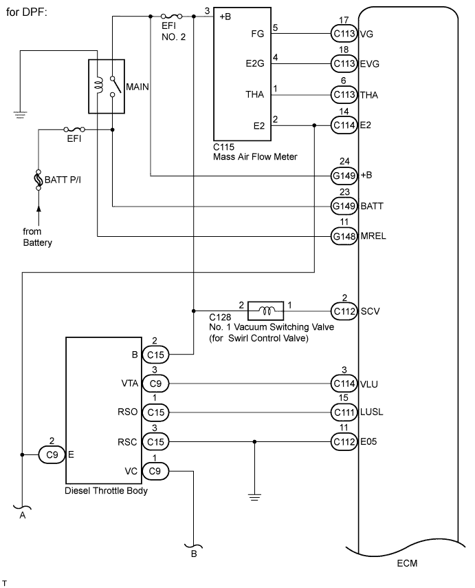
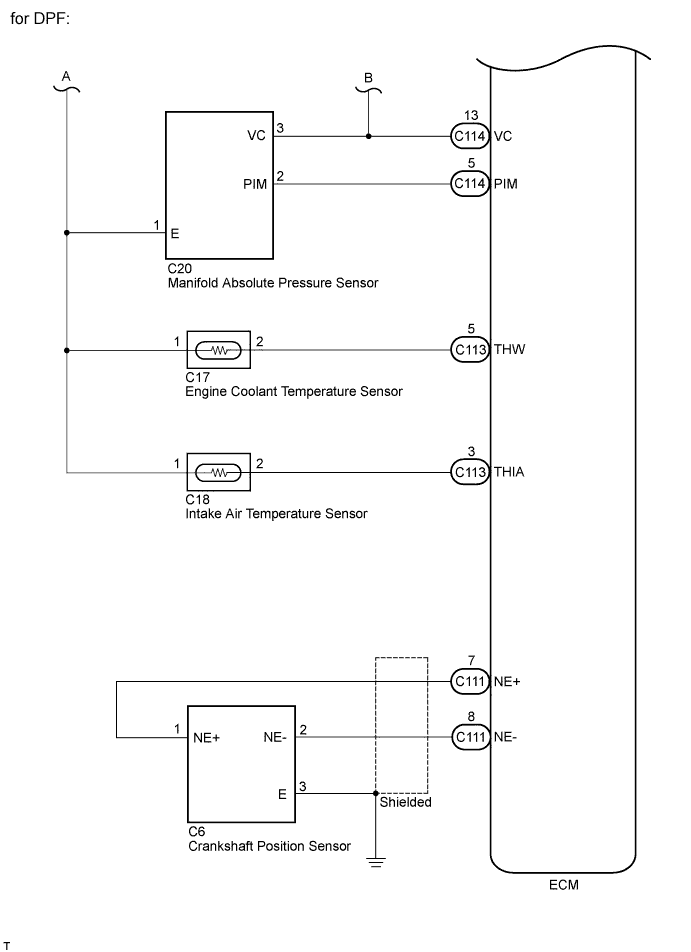
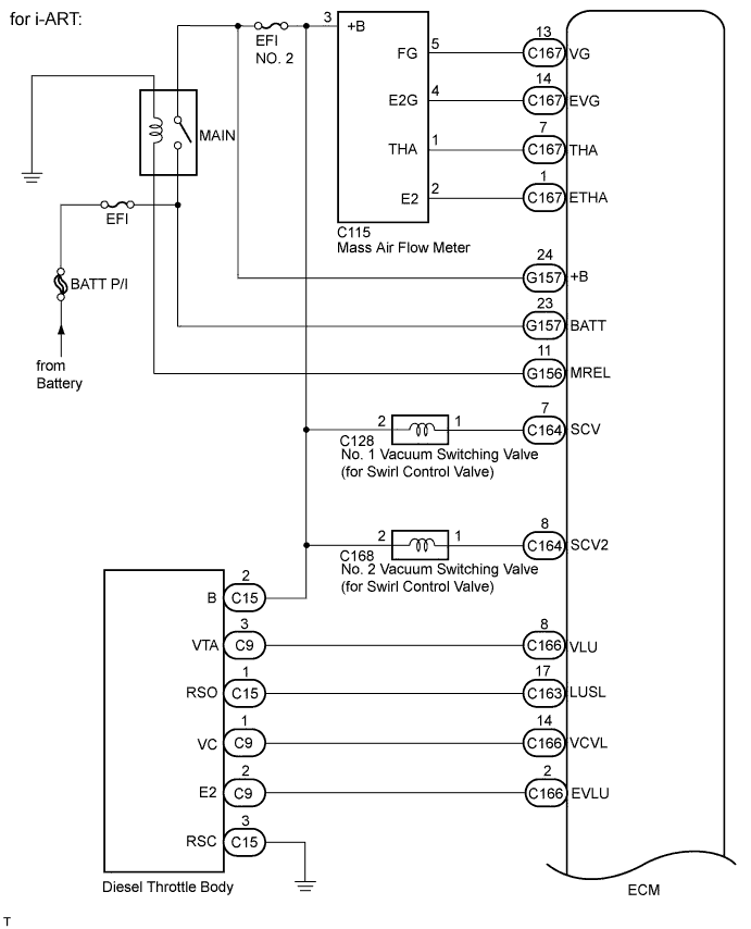
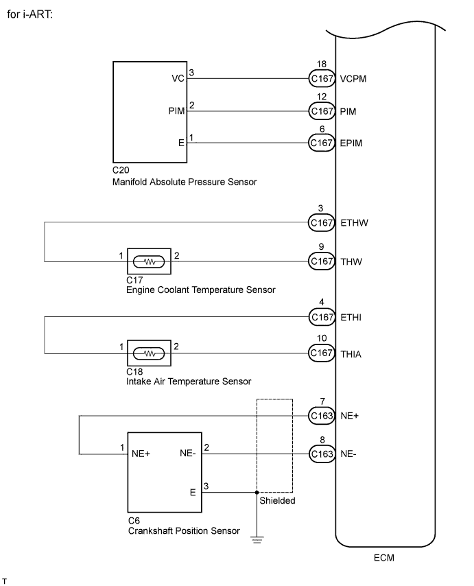
| INTAKE AIR CONTROL SYSTEM WIRING DIAGRAM |
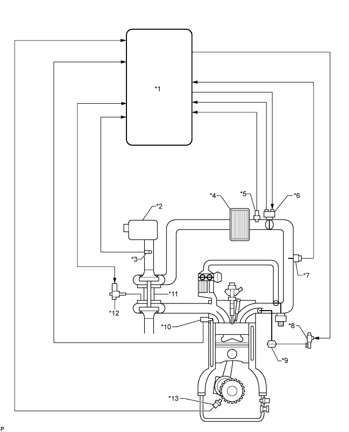
| TURBOCHARGER SYSTEM ILLUSTRATION |
- The turbocharger system is comprised of the Variable Nozzle (VN) type turbocharger and ECM.
- The turbocharger has a nozzle vane which opens and closes to control the volume of the exhaust gas flowing into the turbine. This, in turn, controls the boost pressure. When the nozzle vane moves towards the closing direction, the pressure increases. When the vane moves towards the opening direction, the pressure decreases.
- The turbocharger actuator built onto the compressor housing side activates the nozzle vane. The nozzle vane position sensor built onto the actuator detects the opening angle of the nozzle vane. The ECM receives a nozzle vane position sensor signal. Based on this signal, the ECM operates the DC motor and controls the turbocharger opening angle.
- The ECM performs control to obtain the nozzle vane position for the optimal pressure in accordance with the driving conditions.
| *1 | ECM | *2 | Air Cleaner |
| *3 | Mass Air Flow Meter | *4 | Intercooler |
| *5 | Intake Air Temperature Sensor | *6 | Diesel Throttle Body |
| *7 | Manifold Absolute Pressure Sensor | *8 | No. 1 Vacuum Switching Valve (for Swirl Control Valve) |
| *9 | Swirl Control Valve Actuator | *10 | Engine Coolant Temperature Sensor |
| *11 | Turbocharger | *12 | Turbocharger Actuator - Turbocharger Variable Nozzle Motor - Turbocharger Variable Nozzle Sensor |
| *13 | Crankshaft Position Sensor | - | - |
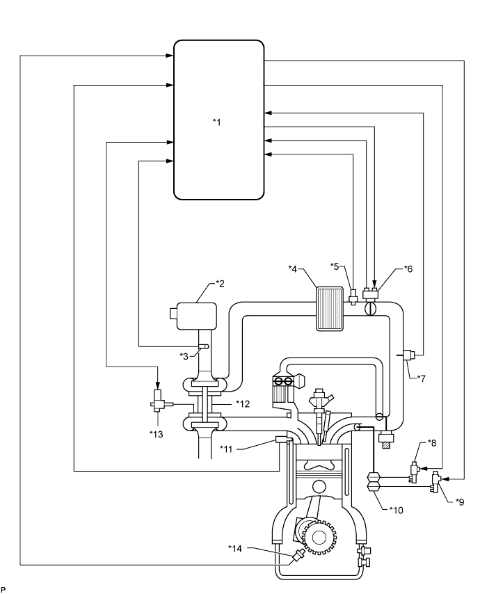
| *1 | ECM | *2 | Air Cleaner |
| *3 | Mass Air Flow Meter | *4 | Intercooler |
| *5 | Intake Air Temperature Sensor | *6 | Diesel Throttle Body |
| *7 | Manifold Absolute Pressure Sensor | *8 | No. 1 Vacuum Switching Valve (for Swirl Control Valve) |
| *9 | No. 2 Vacuum Switching Valve (for Swirl Control Valve) | *10 | Swirl Control Valve Actuator |
| *11 | Engine Coolant Temperature Sensor | *12 | Turbocharger |
| *13 | Turbocharger Actuator - Turbocharger Variable Nozzle Motor - Turbocharger Variable Nozzle Sensor | *14 | Crankshaft Position Sensor |
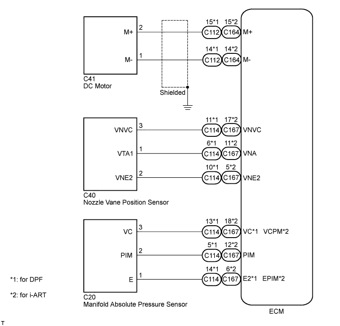
| TURBOCHARGER SYSTEM WIRING DIAGRAM |