Air Conditioning System (For Manual Air Conditioning System) System Description
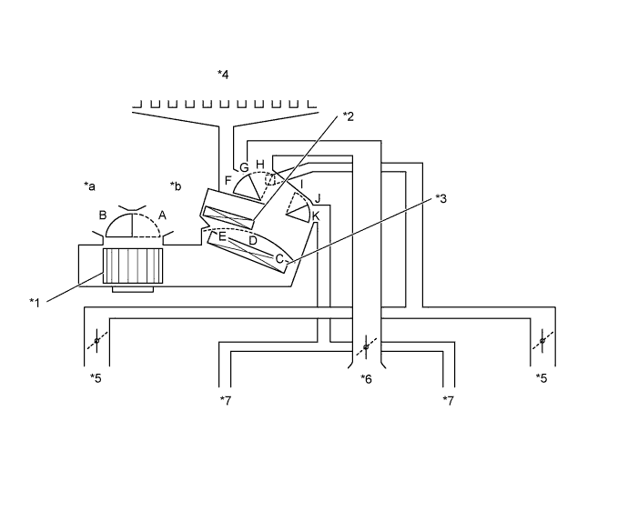
MODE POSITION AND DAMPER OPERATION
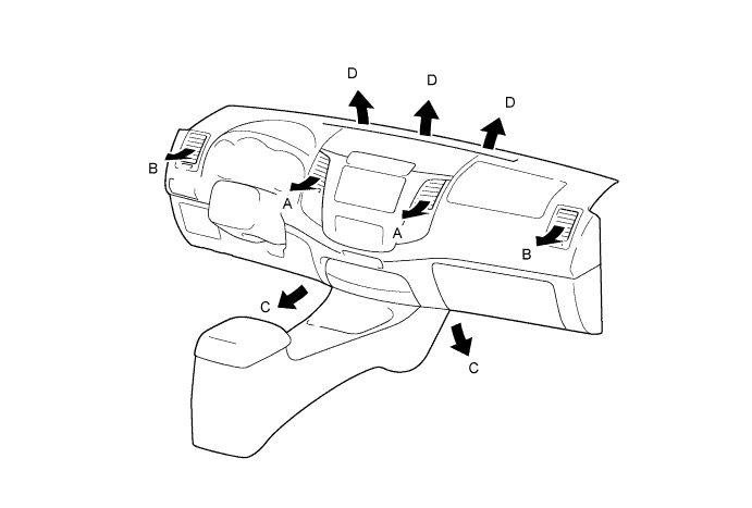
AIR OUTLETS AND AIR FLOW VOLUME
Air Conditioning System (For Manual Air Conditioning System) -- System Description |
| MODE POSITION AND DAMPER OPERATION |
Text in Illustration*1
| Blower with Fan Motor Sub-assembly
| *2
| Heater Radiator Unit Sub-assembly
|
*3
| No. 1 Cooler Evaporator Sub-assembly
| *4
| Front Defroster
|
*5
| Side Register
| *6
| Center Register
|
*7
| Front Footwell Register Duct
| -
| -
|
*a
| Fresh Air
| *b
| Recirculated Air
|
- HINT:
- This Illustration is damper operation image. The number and location of the dampers is different to the actual unit.
Control Damper
| Operation Position
| Damper Position
| Operation
|
Air Inlet Control Damper
| FRESH
| A
| Brings in fresh air.
|
RECIRC
| B
| Recirculates internal air.
|
Air Mix Control Damper
| MAX COLD - MAX HOT
| C, D, E
| Varies mixture ratio of cool air and warm air in order to regulate temperature continuously from HOT to COLD.
|
Mode Damper
| FACE
| 
| F, K
| Air blows out of the center registers and side register.
|
BI-LEVEL
| 
| F, J
| Air blows our of the center registers, side registers and foot well register ducts.
|
FOOT
| 
| G, I
| Air blows out of the foot well register ducts, and side register. In addition, air blows out slightly from the Front defroster.
|
FOOT/DEF
| 
| H, I
| Defrosts the windshield through the front defroster and side register, while air is also blown out from the foot well register ducts.
|
DEF
| 
| H, K
| Defrosts the windshield through the front defroster and side register.
|
| AIR OUTLETS AND AIR FLOW VOLUME |
Indication
| Mode
| A
| B
| C
| D
|
Center
| Side
| Footwell
| Defroster
|
| FACE
| 
|
| -
| -
|
| BI-LEVEL
| 
|
| 
| -
|
| FOOT
| -
|
|
|
|
| FOOT / DEF
| -
|
|
|
|
| DEF
| -
|
| -
|
|
- HINT:
- The circle size (○) is proportional to the amount of air flow.