Cylinder Head Gasket Removal
REMOVE TIMING CHAIN COVER SUB-ASSEMBLY
REMOVE REAR WATER BY-PASS JOINT
SET NO. 1 CYLINDER TO TDC/COMPRESSION
REMOVE NO. 1 CHAIN TENSIONER ASSEMBLY
REMOVE CHAIN TENSIONER SLIPPER
REMOVE NO. 1 IDLE GEAR SHAFT
REMOVE NO. 2 CHAIN VIBRATION DAMPER
REMOVE CHAIN SUB-ASSEMBLY
REMOVE NO. 1 CHAIN VIBRATION DAMPER
REMOVE CAMSHAFT TIMING GEARS AND NO. 2 CHAIN (for Bank 1)
REMOVE NO. 2 CHAIN TENSIONER ASSEMBLY
REMOVE CAMSHAFT TIMING GEARS AND NO. 2 CHAIN (for Bank 2)
REMOVE CAMSHAFT AND NO. 2 CAMSHAFT
REMOVE CYLINDER HEAD SUB-ASSEMBLY
REMOVE NO. 1 CAMSHAFT BEARING
REMOVE NO. 2 CAMSHAFT BEARING
REMOVE CYLINDER HEAD GASKET
REMOVE NO. 3 CHAIN TENSIONER ASSEMBLY
REMOVE NO. 3 CAMSHAFT SUB-ASSEMBLY AND NO. 4 CAMSHAFT SUB-ASSEMBLY
REMOVE CYLINDER HEAD LH
REMOVE NO. 2 CYLINDER HEAD GASKET
INSPECT CYLINDER HEAD SET BOLT
INSPECT CYLINDER HEAD SUB-ASSEMBLY
Cylinder Head Gasket -- Removal |
| 1. REMOVE TIMING CHAIN COVER SUB-ASSEMBLY |
(HILUX_TGN26 RM000000YM200IX.html)
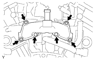
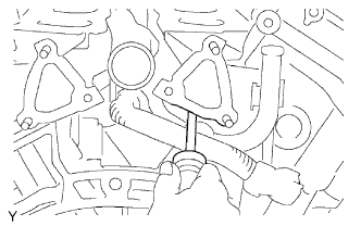
| 2. REMOVE REAR WATER BY-PASS JOINT |
Remove the 2 bolts, 4 nuts, rear water by-pass joint and 2 gaskets.
Remove the O-ring from the No. 1 water outlet pipe.
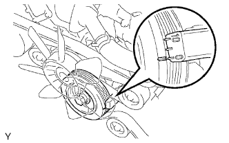
| 3. SET NO. 1 CYLINDER TO TDC/COMPRESSION |
Turn the crankshaft pulley and align its groove with the "0" timing mark of the timing chain cover.
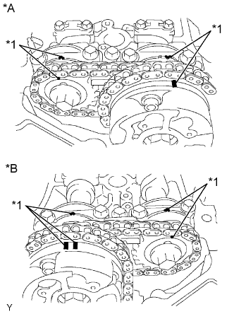
Check that the timing marks of the camshaft timing gears are aligned with the timing marks of the bearing cap as shown in the illustration.
Text in Illustration*A
| for Bank 1
|
*B
| for Bank 2
|
*1
| Timing Mark
|
If not, turn the crankshaft 1 complete revolution (360°) and align the timing marks as above.
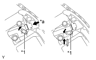
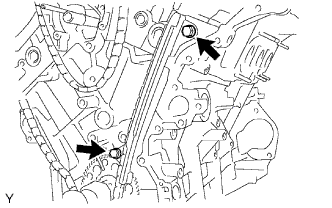
| 4. REMOVE NO. 1 CHAIN TENSIONER ASSEMBLY |
- NOTICE:
- Never rotate the crankshaft with the chain tensioner removed.
- Before rotating the camshaft with the timing chain removed, rotate the crankshaft counterclockwise 40° from TDC first.
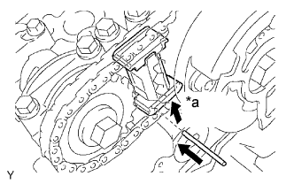
While rotating the stopper plate of the tensioner upward, push in the plunger of the chain tensioner as shown in the illustration.
Text in Illustration*1
| Stopper Plate
|
*a
| Push
|
While rotating the stopper plate of the tensioner downward, insert a bar with a diameter of 3.5 mm (0.138 in.) into the holes in the stopper plate and tensioner to fix the stopper plate in place.
Remove the 2 bolts and No. 1 chain tensioner.
| 5. REMOVE CHAIN TENSIONER SLIPPER |
| 6. REMOVE NO. 1 IDLE GEAR SHAFT |
Using a 10 mm hexagon wrench, remove the No. 2 idle gear shaft, No. 1 idle gear and No. 1 idle gear shaft.
| 7. REMOVE NO. 2 CHAIN VIBRATION DAMPER |
Remove the 2 No. 2 chain vibration dampers.
| 8. REMOVE CHAIN SUB-ASSEMBLY |
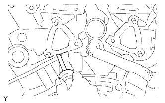
| 9. REMOVE NO. 1 CHAIN VIBRATION DAMPER |
Remove the 2 bolts and No. 1 chain vibration damper.
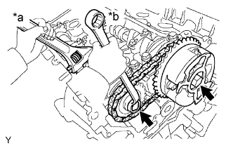
| 10. REMOVE CAMSHAFT TIMING GEARS AND NO. 2 CHAIN (for Bank 1) |
While raising up the No. 2 chain tensioner, insert a pin with a diameter of 1.0 mm (0.0394 in.) into the hole to fix the tensioner in place.
Text in Illustration*a
| Raise
|
Hold the hexagonal portion of the camshaft with a wrench and then remove the 2 bolts, the camshaft timing gear, the camshaft timing gear or sprocket and the No. 2 chain.
Text in Illustration*a
| Hold
|
*b
| Loosen
|
- NOTICE:
- Be careful not to damage the cylinder head and valve lifter with the wrench.
- Do not disassemble the camshaft timing gear.
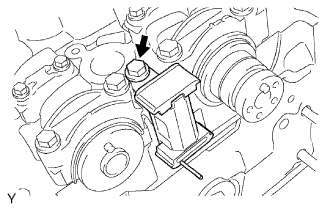
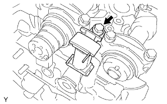
| 11. REMOVE NO. 2 CHAIN TENSIONER ASSEMBLY |
Remove the bolt and No. 2 chain tensioner.
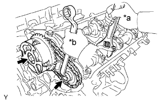
| 12. REMOVE CAMSHAFT TIMING GEARS AND NO. 2 CHAIN (for Bank 2) |
While pushing down the No. 3 chain tensioner, insert a pin with a diameter of 1.0 mm (0.0394 in.) into the hole to fix the tensioner in place.
Text in Illustration*a
| Push
|
Hold the hexagonal portion of the camshaft with a wrench and then remove the 2 bolts, the camshaft timing gear, the camshaft timing gear or sprocket and the No. 2 chain.
Text in Illustration*a
| Hold
|
*b
| Loosen
|
- NOTICE:
- Be careful not to damage the cylinder head and valve lifter with the wrench.
- Do not disassemble the camshaft timing gear.
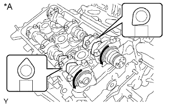
| 13. REMOVE CAMSHAFT AND NO. 2 CAMSHAFT |
- NOTICE:
- As the thrust clearance of the camshaft is small, the camshaft must be kept level while it is being removed. If the camshaft is not kept level, the portion of the cylinder head which received the shaft thrust may crack or be damaged, causing the camshaft to seize or break. To avoid this, the following steps should be carried out.
Remove the camshaft and No. 2 camshaft.
Rotate the camshafts counterclockwise using the hexagonal portion of each camshaft so that the cam lobes of the No. 1 cylinder are oriented as shown in the illustration.
Text in Illustration*A
| for Bank 1
|
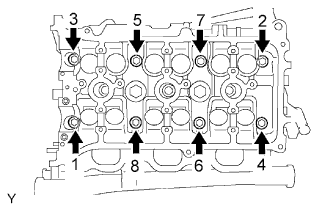
Uniformly loosen and remove the 16 bearing cap bolts in the sequence shown in the illustration.
Text in Illustration*A
| for Bank 1
|
Remove the 8 bearing caps and 2 camshafts.
| 14. REMOVE CYLINDER HEAD SUB-ASSEMBLY |
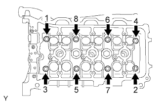
Using a 10 mm bi-hexagon wrench, uniformly loosen the 8 cylinder head bolts in the sequence shown in the illustration. Remove the 8 cylinder head bolts and plate washers.
- NOTICE:
- Be careful not to drop the plate washers into the cylinder head.
- Cylinder head warpage or cracking could result from removing bolts in the incorrect order.
Lift the cylinder head from the dowels on the cylinder block and place the cylinder head on wooden blocks on a bench.
- NOTICE:
- Be careful not to damage the contact surfaces of the cylinder head and cylinder block.
- HINT:
- If the cylinder head is difficult to lift off, pry between the cylinder head and cylinder block with a screwdriver.
| 15. REMOVE NO. 1 CAMSHAFT BEARING |
| 16. REMOVE NO. 2 CAMSHAFT BEARING |
| 17. REMOVE CYLINDER HEAD GASKET |
| 18. REMOVE NO. 3 CHAIN TENSIONER ASSEMBLY |
Remove the bolt and No. 3 chain tensioner.
| 19. REMOVE NO. 3 CAMSHAFT SUB-ASSEMBLY AND NO. 4 CAMSHAFT SUB-ASSEMBLY |
Remove the No. 3 camshaft and No. 4 camshaft.
Uniformly loosen and remove the 16 bearing cap bolts in the sequence shown in the illustration.
Text in Illustration*A
| for Bank 2
|
Remove the 8 bearing caps and 2 camshafts.
| 20. REMOVE CYLINDER HEAD LH |
Uniformly loosen and remove the 2 cylinder head bolts in the sequence shown in the illustration.
Using a 10 mm bi-hexagon wrench, uniformly loosen the 8 cylinder head bolts in the sequence shown in the illustration. Remove the 8 cylinder head bolts and plate washers.
- NOTICE:
- Be careful not to drop the plate washers into the cylinder head LH.
- Cylinder head warpage or cracking could result from removing bolts in the incorrect order.
Lift the cylinder head from the dowels on the cylinder block and place the cylinder head LH on wooden blocks on a bench.
- NOTICE:
- Be careful not to damage the contact surfaces of the cylinder head LH and cylinder block.
- HINT:
- If the cylinder head LH is difficult to lift off, pry between the cylinder head LH and cylinder block with a screwdriver.
| 21. REMOVE NO. 2 CYLINDER HEAD GASKET |
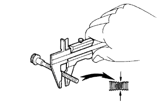
| 22. INSPECT CYLINDER HEAD SET BOLT |
Using a vernier caliper, measure the outside thread diameter of the bolt.
- Standard diameter:
- 10.85 to 11.0 mm (0.427 to 0.433 in.)
- Minimum diameter:
- 10.7 mm (0.421 in.)
If the diameter is less than the minimum, replace the cylinder head set bolt.
| 23. INSPECT CYLINDER HEAD SUB-ASSEMBLY |
Using a precision straightedge and feeler gauge, measure the surfaces that contact the cylinder block and manifolds for warpage.
- Maximum warpage:
- 0.10 mm (0.00394 in.)
Text in Illustration*a
| Cylinder Block Side
|
*b
| Intake Manifold Side
|
*c
| Exhaust Manifold Side
|
If the warpage is more than the maximum, replace the cylinder head sub-assembly.