Dtc U0101 Lost Communication With Tcm
DESCRIPTION
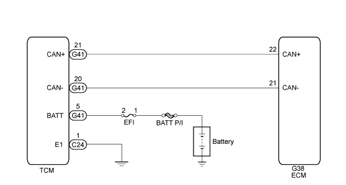
WIRING DIAGRAM
INSPECTION PROCEDURE
CHECK FOR ANY OTHER DTCS OUTPUT (IN ADDITION TO DTC U0101)
INSPECT TCM POWER SOURCE CIRCUIT (POWER SOURCE AND BODY GROUND)
CHECK HARNESS AND CONNECTOR (ECM - TCM)
REPLACE ECM
CHECK WHETHER DTC OUTPUT RECURS (DTC U0101)
DTC U0101 Lost Communication with TCM |
DESCRIPTION
The ECM (engine control unit) communicates with the TCM (transmission control ECU) through the Controller Area Network (CAN).If there is a problem with this communication, the ECM stores a DTC.DTC Detection Drive Pattern
| DTC Detection Condition
| Trouble Area
|
Ignition switch to ON for 3 seconds
| Both conditions are met for 1.25 seconds (1 trip detection logic):
- The battery voltage is 10.5 V or higher.
- No communication between the ECM and TCM.
| - ECM
- TCM
- ECM to TCM circuit
|
WIRING DIAGRAM
INSPECTION PROCEDURE
| 1.CHECK FOR ANY OTHER DTCS OUTPUT (IN ADDITION TO DTC U0101) |
Connect the intelligent tester to the DLC3.
Turn the ignition switch to ON and turn the tester on.
Enter the following menus: Powertrain / Engine and ECT / DTC.
Read the DTCs.
ResultResult
| Proceed to
|
DTC U0101 is output
| A
|
DTC U0101 and other DTCs are output
| B
|
- HINT:
- If any DTCs other than U0101 are output, troubleshoot those DTCs first.
| 2.INSPECT TCM POWER SOURCE CIRCUIT (POWER SOURCE AND BODY GROUND) |
Disconnect the TCM connector.
Measure the voltage according to the value(s) in the table below.
- Standard Voltage:
Tester Connection
| Switch Condition
| Specified Condition
|
G41-5 (BATT) - C24-1 (E1)
| Ignition switch ON
| 11 to 14 V
|
Text in Illustration*a
| Rear view of wire harness connector
(to TCM)
|
Reconnect the TCM connector.
| | REPAIR OR REPLACE HARNESS OR CONNECTOR |
|
|
| 3.CHECK HARNESS AND CONNECTOR (ECM - TCM) |
Disconnect the TCM connector.
Disconnect the ECM connector.
Measure the resistance according to the value(s) in the table below.
- Standard Resistance:
Tester Connection
| Condition
| Specified Condition
|
G38-22 (CAN+) - G41-21 (CAN+)
| Always
| Below 1 Ω
|
G38-21 (CAN-) - G41-20 (CAN-)
| Always
| Below 1 Ω
|
G38-22 (CAN+) or G41-21 (CAN+) - Body ground or other terminals
| Always
| 1 MΩ or higher
|
G38-21 (CAN-) or G41-20 (CAN-) - Body ground or other terminals
| Always
| 1 MΩ or higher
|
Reconnect the TCM connector.
Reconnect the ECM connector.
| | REPAIR OR REPLACE HARNESS OR CONNECTOR |
|
|
Replace the ECM (HILUX_TGN26 RM0000013Z0019X.html).
| 5.CHECK WHETHER DTC OUTPUT RECURS (DTC U0101) |
Connect the intelligent tester to the DLC3.
Turn the ignition switch to ON and turn the tester on.
Enter the following menus: Powertrain / Engine and ECT / DTC.
Read the DTCs.
ResultResult
| Proceed to
|
DTC is not output
| A
|
DTC U0101 is output
| B
|