REMOVE GENERATOR REAR END COVER
REMOVE VOLTAGE REGULATOR SUB-ASSEMBLY WITH BRUSH
REMOVE GENERATOR STATOR SUB-ASSEMBLY WITH RECTIFIER
REMOVE FITTING RING
REMOVE GENERATOR PULLEY
REMOVE GENERATOR ROTOR ASSEMBLY
INSPECT GENERATOR DRIVE END FRAME BEARING
REMOVE GENERATOR DRIVE END FRAME BEARING
| 1. REMOVE GENERATOR REAR END COVER |
Remove the 2 terminal covers by turning them counterclockwise.
Using a 15 mm socket wrench, remove the 2 nuts from the end cover.
Remove the screw and end cover.
| 2. REMOVE VOLTAGE REGULATOR SUB-ASSEMBLY WITH BRUSH |
Remove the 3 screws and regulator.
| 3. REMOVE GENERATOR STATOR SUB-ASSEMBLY WITH RECTIFIER |
Remove the 4 screws.
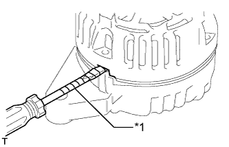
Using a screwdriver, pry out the stator.
Text in Illustration*1
| Protective Tape
|
- HINT:
- Tape the screwdriver tip before use.
| 5. REMOVE GENERATOR PULLEY |
Mount the generator in a vise between aluminum plates.
- NOTICE:
- Do not damage the generator.
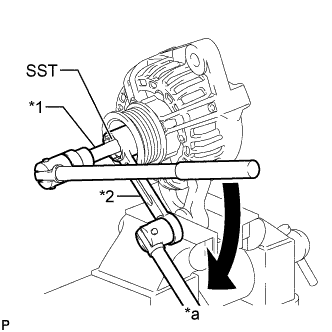
Set SST, a ball joint lock nut wrench and an 8 mm bi-hexagon wrench as shown in the illustration.
- SST
- 09820-30020
Text in Illustration*1
| 8 mm Bi-hexagon Wrench
|
*2
| Ball Joint Lock Nut Wrench
|
*a
| Hold
|

| Turn
|
Hold the 8 mm bi-hexagon wrench in place and turn SST and the ball joint lock nut wrench counterclockwise to loosen the nut.
Remove the nut, washer and generator pulley.
| 6. REMOVE GENERATOR ROTOR ASSEMBLY |
Using a press, press out the rotor, and then remove the spacer ring.
- NOTICE:
- Do not drop the generator rotor assembly.
| 7. INSPECT GENERATOR DRIVE END FRAME BEARING |
Check that the bearing is not rough or worn and that it rotates smoothly.
If necessary, replace the drive end frame bearing.
| 8. REMOVE GENERATOR DRIVE END FRAME BEARING |
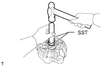
Remove the 4 screws and retainer plate.
Using SST and a hammer, tap out the bearing.
- SST
- 09950-60010(09951-00250)
09950-70010(09951-07100)