Theft Deterrent System Rear Door Courtesy Switch Lh Circuit
DESCRIPTION
WIRING DIAGRAM
INSPECTION PROCEDURE
INSPECT REAR DOOR COURTESY LIGHT SWITCH ASSEMBLY LH
CHECK HARNESS AND CONNECTOR (REAR DOOR COURTESY LIGHT SWITCH LH - THEFT WARNING ECU)
THEFT DETERRENT SYSTEM - Rear Door Courtesy Switch LH Circuit |
DESCRIPTION
The theft warning ECU assembly detects the condition of the rear door courtesy light switch assembly LH.
WIRING DIAGRAM
INSPECTION PROCEDURE
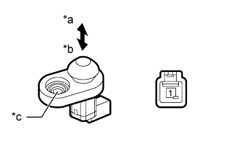
| 1.INSPECT REAR DOOR COURTESY LIGHT SWITCH ASSEMBLY LH |
Remove the rear door courtesy light switch assembly LH (HILUX_TGN26 RM000003YNE015X.html).
Measure the resistance according to the value(s) in the table below.
- Standard Resistance:
Tester Connection
| Switch Condition
| Specified Condition
|
1 - Body ground
| Not pushed (ON)
| Below 1 Ω
|
Pushed (OFF)
| 10 kΩ or higher
|
Text in Illustration*a
| Not pushed (ON)
|
*b
| Pushed (OFF)
|
*c
| Body ground
|
| 2.CHECK HARNESS AND CONNECTOR (REAR DOOR COURTESY LIGHT SWITCH LH - THEFT WARNING ECU) |
Disconnect the K12 rear door courtesy light switch assembly LH connector.
Disconnect the G29 theft warning ECU assembly connector.
Measure the resistance according to the value(s) in the table below.
- Standard Resistance:
Tester Connection
| Condition
| Specified Condition
|
K12-1 - G29-7 (CTY)
| Always
| Below 1 Ω
|
K12-1 or G29-7 (CTY) - Body ground
| Always
| 10 kΩ or higher
|
| | REPAIR OR REPLACE HARNESS OR CONNECTOR |
|
|