Theft Deterrent System Ignition Switch Circuit
DESCRIPTION
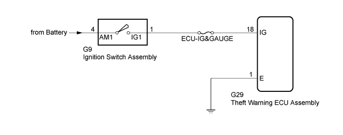
WIRING DIAGRAM
INSPECTION PROCEDURE
INSPECT IGNITION SWITCH ASSEMBLY
CHECK HARNESS AND CONNECTOR (THEFT WARNING ECU - BATTERY AND BODY GROUND)
THEFT DETERRENT SYSTEM - Ignition Switch Circuit |
DESCRIPTION
When the ignition switch assembly is turned to ON, voltage is applied to terminal IG of the theft warning ECU assembly.
WIRING DIAGRAM
INSPECTION PROCEDURE
- NOTICE:
- Inspect the fuses for circuits related to this system before performing the following inspection procedure.
- When replacing the theft warning ECU assembly, refer to the registration procedures (HILUX_TGN26 RM000000Z4Z01KX.html).
| 1.INSPECT IGNITION SWITCH ASSEMBLY |
Remove the ignition switch assembly.
- for 2TR-FE: HILUX_TGN26 RM00000135Z01BX.html
- for 2TR-FBE: HILUX_TGN26 RM00000135Z01GX.html
- for 1KD-FTV: HILUX_TGN26 RM0000013XF01HX.html
- for 2KD-FTV: HILUX_TGN26 RM0000013XF01IX.html
Measure the resistance according to the value(s) in the table below.
- Standard Resistance:
Tester Connection
| Switch Condition
| Specified Condition
|
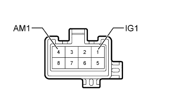
1 (IG1) - 4 (AM1)
| Off, ACC
| 10 kΩ or higher
|
ON, Start
| Below 1 Ω
|
ResultResult
| Proceed to
|
OK
| A
|
NG (for 2TR-FE)
| B
|
NG (for 2TR-FBE)
| C
|
NG (for 1KD-FTV)
| D
|
NG (for 2KD-FTV)
| E
|
| 2.CHECK HARNESS AND CONNECTOR (THEFT WARNING ECU - BATTERY AND BODY GROUND) |
Disconnect the G29 theft warning ECU assembly connector.
Measure the resistance according to the value(s) in the table below.
- Standard Resistance:
Tester Connection
| Condition
| Specified Condition
|
G29-1 (E) - Body ground
| Always
| Below 1 Ω
|
Measure the voltage according to the value(s) in the table below.
- Standard Voltage:
Tester Connection
| Switch Condition
| Specified Condition
|
G29-18 (IG) - Body ground
| Ignition switch off
| Below 1 V
|
Ignition switch ON
| 11 to 14 V
|
Text in Illustration*a
| Front view of wire harness connector
(to Theft Warning ECU Assembly)
|
| | REPAIR OR REPLACE HARNESS OR CONNECTOR |
|
|