Starter (For 1.6 Kw Type) -- Reassembly |
- HINT:
- Use high-temperature grease to lubricate the bearings and sliding parts when assembling the starter.
| 1. INSTALL STARTER CENTER BEARING CLUTCH SUB-ASSEMBLY |
Apply high-temperature grease to the starter drive lever set pin.
Text in Illustration 
High-temperature Grease
 |
Install the drive lever set pin to the starter center bearing clutch sub-assembly.
Text in Illustration *1 Drive Lever Set Pin *2 Starter Center Bearing Clutch
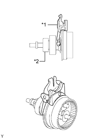 |
Install the starter center bearing clutch and drive lever set pin together to the starter drive housing.
| 2. INSTALL PLANETARY GEAR |
Apply high-temperature grease to the planetary gears and pin parts of the planetary shaft.
Text in Illustration High-temperature Grease
 |
Install the 3 planetary gears onto the pins of the planetary shaft.
| 3. INSTALL STARTER ARMATURE ASSEMBLY |
- NOTICE:
- Do not drop the starter armature assembly.
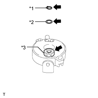
Apply high-temperature grease to the plate washer, a new snap ring and the bearing.
Text in Illustration *1 Snap Ring *2 Plate Washer *3 Bearing High-temperature Grease
 |
Mount the starter commutator end frame in a vise between aluminum plates.
- NOTICE:
- Do not damage the starter commutator end frame.
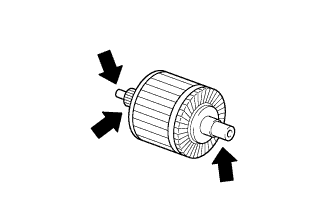
Apply high-temperature grease to the starter armature assembly.
Text in Illustration High-temperature Grease
 |
Install the starter armature assembly to the starter commutator end frame assembly.
Install the plate washer to the starter armature shaft.
Using snap ring pliers, install the snap ring.
- NOTICE:
- Be sure to install the snap ring in the armature shaft groove securely.
- Be sure to properly install the snap ring because it easily expands.
Check the snap ring length.
Using a vernier caliper, measure the snap ring length.
- Maximum length:
- 5.0 mm (0.197 in.)
If the length is more than the maximum, replace the snap ring.Text in Illustration *1 Length
 |
| 4. INSTALL STARTER COMMUTATOR END FRAME COVER |
Install the commutator end frame cover into the starter commutator end frame.
| 5. INSTALL STARTER ARMATURE PLATE |
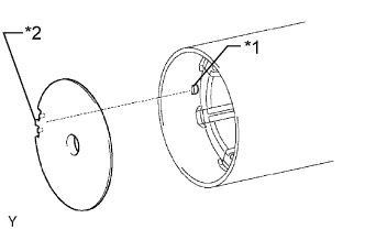
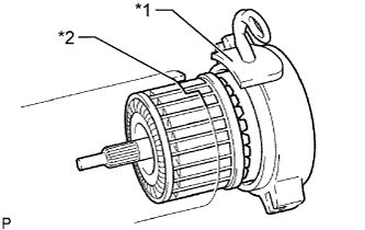
Align the keyway of the starter armature plate with the key inside the starter yoke, and install the starter armature plate.
Text in Illustration *1 key *2 Keyway
 |
| 6. INSTALL STARTER COMMUTATOR END FRAME ASSEMBLY |
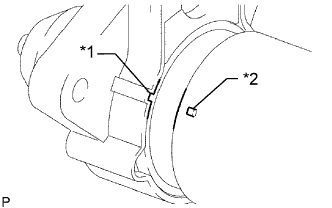
Align the rubber part on the starter commutator end frame with the groove of the starter yoke.
Text in Illustration *1 Rubber Part *2 Groove
 |
Install the starter commutator end frame to the starter yoke.
- NOTICE:
- The magnet of the starter yoke may attract the starter armature when the starter commutator end frame is installed, causing the magnet to break.
| 7. INSTALL STARTER YOKE ASSEMBLY |
Align the claw of the starter yoke with the groove inside the starter drive housing.
Text in Illustration *1 Groove *2 Claw
 |
Install the starter yoke with the 2 through bolts.
- Torque:
- 6.0 N*m{61 kgf*cm, 53 in.*lbf}
| 8. INSTALL REPAIR SERVICE STARTER KIT |
Apply high-temperature grease to the plunger and hook.
Text in Illustration High-temperature Grease
 |
Hang the plunger hook of the repair service starter kit on the drive lever set pin.
Install the plunger and return spring.
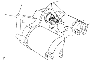 |
Install the repair service starter kit with the 2 screws.
- Torque:
- 7.5 N*m{77 kgf*cm, 66 in.*lbf}
Connect the lead wire to the terminal with the nut.
- Torque:
- 10 N*m{102 kgf*cm, 7 ft.*lbf}