CHECK FRONT POWER WINDOW REGULATOR MOTOR ASSEMBLY LH
POWER WINDOW CONTROL SYSTEM (w/o Jam Protection Function) - Driver Side Power Window Manual Function does not Operate with Power Window Master Switch |
DESCRIPTION
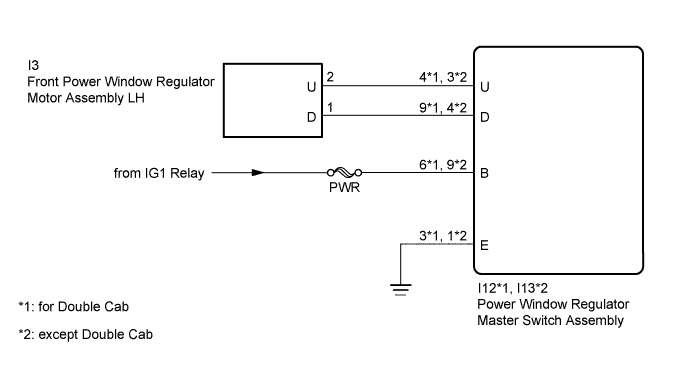
If the manual up/down function does not operate, a malfunction may be present in the power window regulator master switch assembly, front power window regulator motor assembly LH or wire harness.WIRING DIAGRAM
INSPECTION PROCEDURE
- NOTICE:
- Inspect the fuses for circuits related to this system before performing the following inspection procedure.
| 1.CHECK HARNESS AND CONNECTOR (POWER WINDOW REGULATOR MASTER SWITCH ASSEMBLY - BATTERY AND BODY GROUND) |
for Double Cab:
Disconnect the I12 power window regulator master switch assembly connector.
Measure the voltage according to the value(s) in the table below.
- Standard Voltage:
Tester Connection Switch Condition Specified Condition I12-6 (B) - Body ground Ignition switch ON 11 to 14 V Ignition switch off Below 1 V
Measure the resistance according to the value(s) in the table below.
- Standard Resistance:
Tester Connection Condition Specified Condition I12-3 (E) - Body ground Always Below 1 Ω

except Double Cab:
Disconnect the I13 power window regulator master switch assembly connector.
Measure the voltage according to the value(s) in the table below.
- Standard Voltage:
Tester Connection Switch Condition Specified Condition I13-9 (B) - Body ground Ignition switch ON 11 to 14 V Ignition switch off Below 1 V
Measure the resistance according to the value(s) in the table below.
- Standard Resistance:
Tester Connection Condition Specified Condition I13-1 (E) - Body ground Always Below 1 Ω

| *a | Front view of wire harness connector (to Power Window Regulator Master Switch Assembly) |
|
| ||||
| OK | |
| 2.CHECK FRONT POWER WINDOW REGULATOR MOTOR ASSEMBLY LH |
for Double Cab:
Disconnect the I12 power window regulator master switch assembly connector.
Check operation of the front power window regulator motor assembly LH.
- OK:
Measurement Condition Specified Condition Battery positive (+) → I12-4 (U)
Battery negative (-) → I12-9 (D)Power window moves up Battery positive (+) → I12-9 (D)
Battery negative (-) → I12-4 (U)Power window moves down

except Double Cab:
Disconnect the I13 power window regulator master switch assembly connector.
Check operation of the front power window regulator motor assembly LH.
- OK:
Measurement Condition Specified Condition Battery positive (+) → I13-3 (U)
Battery negative (-) → I13-4 (D)Power window moves up Battery positive (+) → I13-4 (D)
Battery negative (-) → I13-3 (U)Power window moves down

| *a | Front view of wire harness connector (to Power Window Regulator Master Switch Assembly) |
|
| ||||
| OK | ||
| ||
| 3.CHECK HARNESS AND CONNECTOR (POWER WINDOW REGULATOR MASTER SWITCH ASSEMBLY - FRONT POWER WINDOW REGULATOR MOTOR ASSEMBLY LH) |
Disconnect the I12*1 or I13*2 power window regulator master switch assembly connector.
- *1: for Double Cab
- *2: except Double Cab
- *1: for Double Cab
Disconnect the I3 front power window regulator motor assembly LH connector.
Measure the resistance according to the value(s) in the table below.
- Standard Resistance:
for Double Cab Tester Connection Condition Specified Condition I12-9 (D) - I3-1 (D) Always Below 1 Ω I12-4 (U) - I3-2 (U) Always Below 1 Ω I12-9 (D) or I3-1 (D) - Body ground Always 10 kΩ or higher I12-4 (U) or I3-2 (U) - Body ground Always 10 kΩ or higher except Double Cab Tester Connection Condition Specified Condition I13-4 (D) - I3-1 (D) Always Below 1 Ω I13-3 (U) - I3-2 (U) Always Below 1 Ω I13-9 (D) or I3-1 (D) - Body ground Always 10 kΩ or higher I13-3 (U) or I3-2 (U) - Body ground Always 10 kΩ or higher
|
| ||||
| OK | ||
| ||