Dtc 12 Ambient Temperature Sensor Circuit
DESCRIPTION
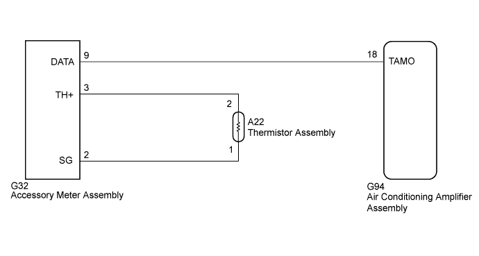
WIRING DIAGRAM
INSPECTION PROCEDURE
CHECK ACCESSORY METER ASSEMBLY
CHECK HARNESS AND CONNECTOR (ACCESSORY METER - AIR CONDITIONING AMPLIFIER)
INSPECT THERMISTOR ASSEMBLY
CHECK HARNESS AND CONNECTOR (ACCESSORY METER - THERMISTOR)
DTC 12 Ambient Temperature Sensor Circuit |
DESCRIPTION
The thermistor assembly connected to the accessory meter detects fluctuations in the ambient temperature. This information is used for controlling the interior temperature. The accessory meter detects the resistance of the thermistor assembly and sends this information to the air conditioning amplifier assembly.DTC Code
| DTC Detection Condition
| Trouble Area
|
12
| An open or short in ambient temperature sensor circuit
| - Thermistor assembly
- Accessory meter assembly
- Air conditioning amplifier assembly
- Harness or connector
|
WIRING DIAGRAM
INSPECTION PROCEDURE
- NOTICE:
- Check that the accessory meter assembly illuminates normally before performing the following inspection procedure.
| 1.CHECK ACCESSORY METER ASSEMBLY |
Check the difference between the ambient temperature value displayed on the accessory meter assembly and the actual ambient temperature.
- OK:
- The ambient temperature displayed on the accessory meter assembly and the actual ambient temperature are almost the same.
- HINT:
- The temperature displayed on the accessory meter assembly and the actual temperature detected by the thermistor assembly may differ when the ambient temperature changes significantly (for example, when the vehicle is entering/exiting tunnels, or the vehicle speed or wind direction changes).
| 2.CHECK HARNESS AND CONNECTOR (ACCESSORY METER - AIR CONDITIONING AMPLIFIER) |
Disconnect the G32 accessory meter assembly connector.
Disconnect the G94 air conditioning amplifier assembly connector.
Measure the resistance according to the value(s) in the table below.
- Standard Resistance:
Tester Connection
| Condition
| Specified Condition
|
G32-9 (DATA) - G94-18 (TAMO)
| Always
| Below 1 Ω
|
G32-9 (DATA) - Body ground
| Always
| 10 kΩ or higher
|
ResultResult
| Proceed to
|
OK (When troubleshooting according to problem symptoms table.)
| A
|
OK (When troubleshooting according to DTC.)
| B
|
NG
| C
|
| |
|
| | REPAIR OR REPLACE HARNESS OR CONNECTOR |
|
|
| 3.INSPECT THERMISTOR ASSEMBLY |
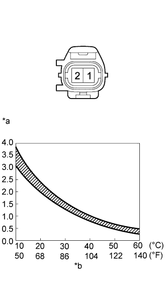
Remove the thermistor assembly (HILUX_TGN26 RM000002VYK01LX.html).
Measure the resistance according to the value(s) in the table below.
- Standard Resistance:
Tester Connection
| Condition
| Specified Condition
|
1 - 2
| 10°C (50°F)
| 3.00 to 3.73 kΩ
|
15°C (59°F)
| 2.45 to 2.88 kΩ
|
20°C (68°F)
| 1.95 to 2.30 kΩ
|
25°C (77°F)
| 1.60 to 1.80 kΩ
|
30°C (86°F)
| 1.28 to 1.47 kΩ
|
35°C (95°F)
| 1.00 to 1.22 kΩ
|
40°C (104°F)
| 0.80 to 1.00 kΩ
|
45°C (113°F)
| 0.65 to 0.85 kΩ
|
50°C (122°F)
| 0.50 to 0.70 kΩ
|
55°C (131°F)
| 0.44 to 0.60 kΩ
|
60°C (140°F)
| 0.36 to 0.50 kΩ
|
Text in Illustration*a
| Resistance (kΩ)
|
*b
| Temperature
|
- NOTICE:
- Even slightly touching the thermistor assembly may change the resistance value. Be sure to hold the connector of the thermistor assembly.
- When measuring the resistance, the thermistor assembly temperature must be the same as the ambient temperature.
- HINT:
- As the temperature increases, the resistance decreases (Refer to the graph).
| 4.CHECK HARNESS AND CONNECTOR (ACCESSORY METER - THERMISTOR) |
Disconnect the G32 accessory meter assembly connector.
Disconnect the A22 thermistor assembly connector.
Measure the resistance according to the value(s) in the table below.
- Standard Resistance:
Tester Connection
| Condition
| Specified Condition
|
G32-3 (TH+) - A22-2
| Always
| Below 1 Ω
|
G32-2 (SG) - A22-1
|
G32-3 (TH+) - Body ground
| Always
| 10 kΩ or higher
|
G32-2 (SG) - Body ground
|
| | REPAIR OR REPLACE HARNESS OR CONNECTOR |
|
|