Power Window Control System (W/ Jam Protection Function) Auto Up / Down Function Does Not Operate
DESCRIPTION
WIRING DIAGRAM
INSPECTION PROCEDURE
CHECK MANUAL UP/DOWN FUNCTION (FOR DRIVER SIDE)
CHECK LIGHT OF POWER WINDOW REGULATOR MASTER SWITCH ASSEMBLY
RESET FRONT POWER WINDOW REGULATOR MOTOR ASSEMBLY LH
CHECK HARNESS AND CONNECTOR (POWER WINDOW REGULATOR MASTER SWITCH ASSEMBLY - FRONT POWER WINDOW REGULATOR MOTOR ASSEMBLY LH)
CHECK POWER WINDOW REGULATOR MASTER SWITCH ASSEMBLY (PLS, PLS2 SIGNAL)
POWER WINDOW CONTROL SYSTEM (w/ Jam Protection Function) - Auto Up / Down Function does not Operate |
DESCRIPTION
If the auto up/down function does not operate, the cause may be one or more of the following:- The recorded power window fully closed position, which is stored in the power window regulator master switch assembly, was erased as a result of: 1) the PWR H-fuse or DOOR fuse being replaced; or 2) the battery cable and the master switch's connector being disconnected.
- The power window regulator master switch assembly has a malfunction.
- The pulse sensors in the front power window regulator motor assembly LH have a malfunction.
- The wiring between the power window regulator master switch assembly and the front power window regulator motor assembly RH is open or short-circuited.
WIRING DIAGRAM
INSPECTION PROCEDURE
| 1.CHECK MANUAL UP/DOWN FUNCTION (FOR DRIVER SIDE) |
Check that the manual up/down function operates normally.
- OK:
- Manual up/down function operates normally.
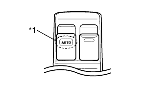
| 2.CHECK LIGHT OF POWER WINDOW REGULATOR MASTER SWITCH ASSEMBLY |
Turn the ignition switch to ON.
Operate the master switch's driver side power window switch for 2 seconds or more.
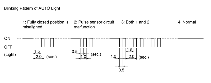
Check the blinking pattern of the AUTO light. Compare the blinking pattern with the illustration.
Text in Illustration*1
| AUTO Light
|
ResultBlinking Pattern
| Proceed to
|
1 or 3
| A
|
2
| B
|
4
| C
|
| 3.RESET FRONT POWER WINDOW REGULATOR MOTOR ASSEMBLY LH |
Check that the power window operates normally after reset (HILUX_TGN26 RM000001DJB01FX.html).
- OK:
- Power window operates normally.
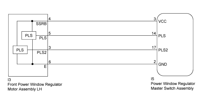
| 4.CHECK HARNESS AND CONNECTOR (POWER WINDOW REGULATOR MASTER SWITCH ASSEMBLY - FRONT POWER WINDOW REGULATOR MOTOR ASSEMBLY LH) |
Disconnect the I5 power window regulator master switch assembly connector.
Disconnect the I3 front power window regulator motor assembly LH connector.
Measure the resistance according to the value(s) in the table below.
- Standard Resistance:
Tester Connection
| Condition
| Specified Condition
|
I5-3 (VCC) - I3-4 (SSRB)
| Always
| Below 1 Ω
|
I5-14 (PLS) - I3-5 (PLS)
| Always
| Below 1 Ω
|
I5-17 (PLS2) - I3-3 (PLS2)
| Always
| Below 1 Ω
|
I5-2 (GND) - I3-6 (E)
| Always
| Below 1 Ω
|
I5-3 (VCC) or I3-4 (SSRB) - Body ground
| Always
| 10 kΩ or higher
|
I5-14 (PLS) or I3-5 (PLS) - Body ground
| Always
| 10 kΩ or higher
|
I5-17 (PLS2) or I3-3 (PLS2) - Body ground
| Always
| 10 kΩ or higher
|
| | REPAIR OR REPLACE HARNESS OR CONNECTOR |
|
|
| 5.CHECK POWER WINDOW REGULATOR MASTER SWITCH ASSEMBLY (PLS, PLS2 SIGNAL) |
Remove the power window regulator master switch assembly with its connectors still connected (HILUX_TGN26 RM000002STU07WX.html).
Using an oscilloscope, check the waveform.
- OK:
Tester Connection
| Switch Condition
| Specified Condition
|
I5-14 (PLS) - Body ground
| Ignition switch ON, driver side power window switch off → up or down
| Pulse waveform is output
|
I5-17 (PLS2) - Body ground
|
Text in Illustration*a
| Component with harness connected
(Power Window Regulator Master Switch Assembly)
|