Generator -- Inspection |
| 1. INSPECT GENERATOR ROTOR ASSEMBLY |
Check that the bearing is not rough or worn and that it rotates smoothly.
If necessary, replace the generator rotor assembly.
 |
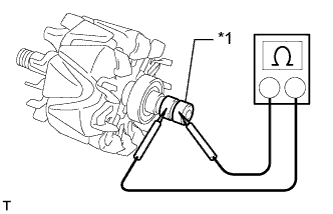
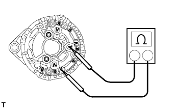
Check the resistance.
Measure the resistance according to the value(s) in the table below.
- Standard Resistance:
Tester Connection Condition Specified Condition Slip Ring - Slip Ring 20°C (68°F) 1.8 to 2.8 Ω
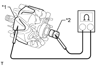
If the result is not as specified, replace the generator rotor assembly.Text in Illustration *1 Slip Ring Measure the resistance according to the value(s) in the table below.
- Standard Resistance:
Tester Connection Condition Specified Condition Slip Ring - Rotor Core Always 10 kΩ or higher
If the result is not as specified, replace the generator rotor assembly.Text in Illustration *1 Rotor Core *2 Slip Ring
Check each slip ring.
Check that the slip rings are not rough or scored.
If rough or scored, replace the generator rotor assembly.Using a vernier caliper, measure the slip ring diameter.
- Standard diameter:
- 15.3 to 15.5 mm (0.602 to 0.610 in.)
- Minimum diameter:
- 14.9 mm (0.587 in.)

| 2. INSPECT GENERATOR STATOR SUB-ASSEMBLY WITH RECTIFIER |
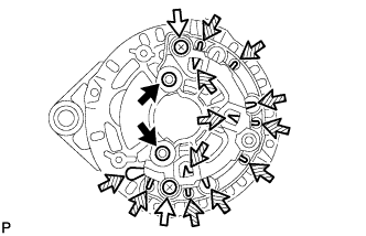 |
 | Positive (+) Terminal |
 | Negative (-) Terminal |
 | Rectifier Terminal |
- HINT:
- For terminal positions of the stator generator, refer to the illustration below.
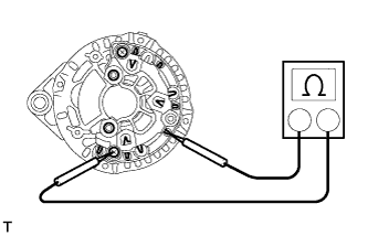
Inspect the positive (+) rectifier.
- HINT:
- Inspect the positive (+) terminal after pulling it up.
Using an ohmmeter, connect one tester probe to the positive (+) terminal and the other to each rectifier terminal.
Reverse the polarity of the tester probes and repeat the step above.
Check that one shows a resistance of below 1 Ω and the other shows a resistance of 10 kΩ or higher.
If the result is not as specified, replace the generator stator sub-assembly with rectifier.
 |
Inspect the negative (-) rectifier.
Using an ohmmeter, connect one tester probe to each negative (-) terminal and the other to each rectifier terminal.
Reverse the polarity of the tester probes and repeat the step above.
Check that one shows a resistance of below 1 Ω and the other shows a resistance of 10 kΩ or higher.
If the result is not as specified, replace the generator stator sub-assembly with rectifier.
 |
Inspect the stator coil for an open circuit.
Measure the resistance according to the value(s) in the table below.
- Standard Resistance:
Tester Connection Condition Specified Condition Rectifier Terminal - Rectifier Terminal Always Below 1 Ω
 |
| 3. INSPECT VOLTAGE REGULATOR SUB-ASSEMBLY WITH BRUSH |
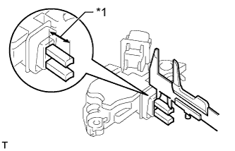
Using a vernier caliper, measure the exposed brush length.
- Standard exposed length:
- 13.2 mm (0.520 in.)
- Minimum exposed length:
- 6.0 mm (0.236 in.)
If the exposed length is less than the minimum, replace the voltage regulator sub-assembly with brush.Text in Illustration *1 Length
 |