Dtc P0405 Exhaust Gas Recirculation Sensor A Circuit Low
DESCRIPTION
MONITOR DESCRIPTION
WIRING DIAGRAM
INSPECTION PROCEDURE
CHECK TERMINAL VOLTAGE (EGR VALVE POSITION SENSOR CONNECTOR)
INSPECT EGR VALVE POSITION SENSOR
CHECK HARNESS AND CONNECTOR (EGR VALVE POSITION SENSOR - ECM)
REPLACE ECM
REPLACE ELECTRIC EGR CONTROL VALVE ASSEMBLY
REPAIR OR REPLACE HARNESS OR CONNECTOR
CONFIRM WHETHER MALFUNCTION HAS BEEN SUCCESSFULLY REPAIRED
DTC P0405 Exhaust Gas Recirculation Sensor "A" Circuit Low |
DTC P0406 Exhaust Gas Recirculation Sensor "A" Circuit High |
DESCRIPTION
The EGR valve position sensor is mounted on the EGR valve and is used for detecting the lift amount of the valve. The lift amount detected by the sensor is provided to the ECM as feedback. The ECM then regulates the lift amount of the valve in accordance with engine running conditions.P0405DTC Detection Drive Pattern
| DTC Detection Condition
| Trouble Area
|
Ignition switch to ON for 5 seconds
| EGR valve position sensor output voltage is below 0.1 V for more than 5 seconds (1 trip detection logic).
| - Open or short in EGR valve position sensor circuit
- EGR valve position sensor
- ECM
|
P0406DTC Detection Drive Pattern
| DTC Detection Condition
| Trouble Area
|
Ignition switch to ON for 5 seconds
| EGR valve position sensor output voltage is more than 4.9 V for higher than 5 seconds (1 trip detection logic).
| - Open or short in EGR valve position sensor circuit
- EGR valve position sensor
- ECM
|
MONITOR DESCRIPTION
When the output voltage of the EGR valve position sensor deviates from the normal operating range of 0.1 to 4.9 V for more than 5 seconds, the ECM interprets this as a malfunction of the sensor circuit and illuminates the MIL.
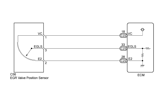
WIRING DIAGRAM
INSPECTION PROCEDURE
- NOTICE:
- After replacing the ECM, the new ECM needs registration (HILUX_TGN26 RM0000012XK05EX.html) and initialization (HILUX_TGN26 RM000000TIN04BX.html).
- HINT:
- Read freeze frame data using the intelligent tester. The ECM records vehicle and driving condition information as freeze frame data the moment a DTC is stored. When troubleshooting, freeze frame data can help determine if the vehicle was moving or stationary, if the engine was warmed up or not, and other data from the time the malfunction occurred.
| 1.CHECK TERMINAL VOLTAGE (EGR VALVE POSITION SENSOR CONNECTOR) |
Disconnect the EGR valve position sensor connector.
Measure the voltage according to the value(s) in the table below.
- Standard Voltage:
Tester Connection
| Switch Condition
| Specified Condition
|
C56-1 (VC) - C56-2 (E2)
| Ignition switch ON
| 4.5 to 5.5 V
|
Text in Illustration*a
| Front view of wire harness connector
(to EGR Valve Position Sensor)
|
Reconnect the electric vacuum regulating valve assembly connector.
| 2.INSPECT EGR VALVE POSITION SENSOR |
Inspect the EGR valve position sensor (HILUX_TGN26 RM000002RK7013X.html).
| 3.CHECK HARNESS AND CONNECTOR (EGR VALVE POSITION SENSOR - ECM) |
Disconnect the EGR valve position sensor connector.
Disconnect the ECM connectors.
Measure the resistance according to the value(s) in the table below.
- Standard Resistance:
Tester Connection
| Condition
| Specified Condition
|
C56-1 (VC) - C22-18 (VC)
| Always
| Below 1 Ω
|
C56-3 (EGLS) - C23-33 (EGLS)
| Always
| Below 1 Ω
|
C56-2 (E2) - C22-28 (E2)
| Always
| Below 1 Ω
|
C56-1 (VC) or C22-18 (VC) - Body ground
| Always
| 10 kΩ or higher
|
C56-3 (EGLS) or C23-33 (EGLS) - Body ground
| Always
| 10 kΩ or higher
|
Reconnect the electric vacuum regulating valve assembly connector.
Reconnect the ECM connector.
Replace the ECM (HILUX_TGN26 RM0000013Z001HX.html).
| 5.REPLACE ELECTRIC EGR CONTROL VALVE ASSEMBLY |
Replace the electric EGR control valve assembly (HILUX_TGN26 RM000002RK9021X.html).
| 6.REPAIR OR REPLACE HARNESS OR CONNECTOR |
Repair or replace the harness or connector.
| 7.CONFIRM WHETHER MALFUNCTION HAS BEEN SUCCESSFULLY REPAIRED |
Connect the intelligent tester to the DLC3.
Clear the DTCs (HILUX_TGN26 RM000000PDK0XEX.html).
Turn the ignition switch to ON for 5 seconds or more.
Enter the following menus: Powertrain / Engine and ECT / DTC.
Confirm that the DTC is not output again.