Steering Gear Installation
Steering. Hilux. Tgn26, 36 Kun25, 26, 35, 36 Ggn25
INSTALL POWER STEERING LINK ASSEMBLY
INSTALL FRONT STABILIZER BAR
CONNECT STEERING GEAR OUTLET RETURN TUBE
CONNECT PRESSURE FEED TUBE ASSEMBLY
CONNECT NO. 2 STEERING INTERMEDIATE SHAFT SUB-ASSEMBLY
CONNECT STEERING SLIDING YOKE
CONNECT TIE ROD END SUB-ASSEMBLY LH
CONNECT TIE ROD END SUB-ASSEMBLY RH
INSTALL FRONT SIDE MEMBER TO FRONT SUSPENSION CROSSMEMBER BRACE
INSTALL NO. 1 ENGINE UNDER COVER
INSTALL NO. 2 ENGINE UNDER COVER
INSTALL FRONT WHEELS
ADD POWER STEERING FLUID
ADJUST POWER STEERING FLUID
CHECK POWER STEERING FLUID LEAK
ADJUST FRONT WHEEL ALIGNMENT
Steering Gear -- Installation |
| 1. INSTALL POWER STEERING LINK ASSEMBLY |
Install the steering link with the 2 bolts and 2 nuts.
- Torque:
- 95 N*m{969 kgf*cm, 70 ft.*lbf}
- HINT:
- If necessary, return the differential to its original position and install the differential mount.
| 2. INSTALL FRONT STABILIZER BAR |
(HILUX_TGN26 RM0000010OV00XX.html)
| 3. CONNECT STEERING GEAR OUTLET RETURN TUBE |
Using a union nut wrench, connect the outlet return tube.
- Torque:
- 44 N*m{449 kgf*cm, 33 ft.*lbf}
- NOTICE:
- Use the formula to calculate special torque values for situations where a union nut wrench is combined with a torque wrench (HILUX_TGN26 RM000004QR1006X.html).
Install the hose with the clip.
| 4. CONNECT PRESSURE FEED TUBE ASSEMBLY |
Install the pressure feed tube to the steering link with the bolt.
- Torque:
- 28 N*m{286 kgf*cm, 21 ft.*lbf}
Using a union nut wrench, tighten the flare nut and connect the pressure feed tube.
- Torque:
- 44 N*m{449 kgf*cm, 33 ft.*lbf}
- NOTICE:
- Use the formula to calculate special torque values for situations where a union nut wrench is combined with a torque wrench (HILUX_TGN26 RM000004QR1006X.html).
| 5. CONNECT NO. 2 STEERING INTERMEDIATE SHAFT SUB-ASSEMBLY |
Align the matchmarks on the steering intermediate shaft and steering link.
Install the bolt.
- Torque:
- 35 N*m{357 kgf*cm, 26 ft.*lbf}
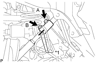
| 6. CONNECT STEERING SLIDING YOKE |
Align the matchmarks on the steering sliding yoke and steering intermediate shaft, and connect the steering sliding yoke to the steering intermediate shaft.
Text in Illustration*1
| Matchmark
|
Install the bolt labeled B.
- Torque:
- 35 N*m{357 kgf*cm, 26 ft.*lbf}
Tighten the bolt labeled A.
- Torque:
- 35 N*m{357 kgf*cm, 26 ft.*lbf}
| 7. CONNECT TIE ROD END SUB-ASSEMBLY LH |
Connect the tie rod end to the steering knuckle arm with the nut.
- Torque:
- 91 N*m{928 kgf*cm, 67 ft.*lbf}
Install a new cotter pin.
- NOTICE:
- If the holes for the cotter pin are not aligned, tighten the nut an additional 60°.
| 8. CONNECT TIE ROD END SUB-ASSEMBLY RH |
- HINT:
- Use the same procedure described for the LH side.
| 9. INSTALL FRONT SIDE MEMBER TO FRONT SUSPENSION CROSSMEMBER BRACE |
Install the 2 crossmember braces with the 10 bolts.
- Torque:
- 50 N*m{510 kgf*cm, 37 ft.*lbf}
| 10. INSTALL NO. 1 ENGINE UNDER COVER |
Install the under cover with the 4 bolts.
- Torque:
- 28 N*m{286 kgf*cm, 21 ft.*lbf}
| 11. INSTALL NO. 2 ENGINE UNDER COVER |
Install the under cover with the 4 bolts.
- Torque:
- 28 N*m{286 kgf*cm, 21 ft.*lbf}
- Torque:
- 105 N*m{1071 kgf*cm, 77 ft.*lbf}
| 13. ADD POWER STEERING FLUID |
| 14. ADJUST POWER STEERING FLUID |
(HILUX_TGN26 RM00000138601YX.html)
| 15. CHECK POWER STEERING FLUID LEAK |
| 16. ADJUST FRONT WHEEL ALIGNMENT |
(HILUX_TGN26 RM0000037JW00RX.html)