Dtc P0660 Intake Manifold Tuning Valve Control Circuit / Open (Bank 1)
DESCRIPTION
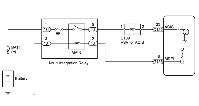
WIRING DIAGRAM
INSPECTION PROCEDURE
PERFORM ACTIVE TEST USING INTELLIGENT TESTER (ACTIVATE THE VSV FOR INTAKE CONTROL)
INSPECT VSV FOR ACIS (RESISTANCE)
INSPECT VSV FOR ACIS (POWER SOURCE)
CHECK HARNESS AND CONNECTOR (VSV FOR ACIS - ECM)
CHECK HARNESS AND CONNECTOR (VSV FOR ACIS - NO. 1 INTEGRATION RELAY)
DTC P0660 Intake Manifold Tuning Valve Control Circuit / Open (Bank 1) |
DESCRIPTION
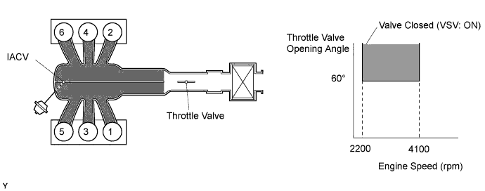
This circuit opens and closes the Intake Air Control Valve (IACV) in response to changes in the engine load in order to increase the intake efficiency (ACIS: Acoustic Control Induction System).When the engine speed is between 2200 rpm and 4100 rpm and the throttle valve opening angle is 60° or more, the ECM supplies current to the VSV (ON status) to close the IACV. Under other conditions, the VSV is usually OFF and the IACV is open.DTC No.
| DTC Detection Condition
| Trouble Area
|
P0660
| Conditions (a) and (b) are met for 0.5 seconds or more (2 trip detection logic):
(a) The voltage of terminal ACIS of the ECM is low when the VSV is OFF.
(b) The engine has started.
| - Open or short in VSV for ACIS circuit
- VSV for ACIS
- ECM
|
WIRING DIAGRAM
INSPECTION PROCEDURE
- NOTICE:
- Inspect the fuses for circuits related to this system before performing the following inspection procedure.
- HINT:
- Read freeze frame data using the intelligent tester. Freeze frame data records the engine condition when malfunctions are detected. When troubleshooting, freeze frame data can help determine if the vehicle was moving or stationary, if the engine was warmed up or not, if the air-fuel ratio was lean or rich, and other data from the time the malfunction occurred.
| 1.PERFORM ACTIVE TEST USING INTELLIGENT TESTER (ACTIVATE THE VSV FOR INTAKE CONTROL) |
Connect the intelligent tester to the DLC3.
Start the engine and turn the tester on.
Enter the following menus: Powertrain / Engine and ECT / Active Test / Activate the VSV for Intake Control.
Check if an operating noise can be heard when operating the air intake control valve using the intelligent tester.
- OK:
- Operating noise can be heard.
| 2.INSPECT VSV FOR ACIS (RESISTANCE) |
Check the VSV for ACIS (HILUX_TGN26 RM0000014ZM00LX_01_0001.html).
| 3.INSPECT VSV FOR ACIS (POWER SOURCE) |
Disconnect the VSV for ACIS connector.
Measure the voltage according to the value(s) in the table below.
- Standard Voltage:
Tester Connection
| Switch Condition
| Specified Condition
|
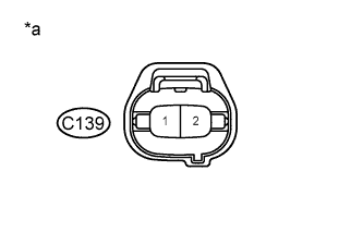
C139-1 - Body ground
| Ignition switch ON
| 11 to 14 V
|
Text in Illustration*a
| Front view of wire harness connector
(to VSV for ACIS)
|
| 4.CHECK HARNESS AND CONNECTOR (VSV FOR ACIS - ECM) |
Disconnect the VSV for ACIS connector.
Disconnect the ECM connector.
Measure the resistance according to the value(s) in the table below.
- Standard Resistance :
Tester Connection
| Condition
| Specified Condition
|
C139-2 - C129-33 (ACIS)
| Always
| Below 1 Ω
|
C139-2 or C129-33 (ACIS) - Body ground
| Always
| 10 kΩ or higher
|
| | REPAIR OR REPLACE HARNESS OR CONNECTOR |
|
|
| 5.CHECK HARNESS AND CONNECTOR (VSV FOR ACIS - NO. 1 INTEGRATION RELAY) |
Disconnect the VSV for ACIS connector.
Remove the No. 1 integration relay from the engine room relay block and junction block assembly.
Measure the resistance according to the value(s) in the table below.
- Standard Resistance:
Tester Connection
| Condition
| Specified Condition
|
C139-1 - 1J-5
| Always
| Below 1 Ω
|
C139-1 or 1J-5 - Body ground
| Always
| 10 kΩ or higher
|
| | REPAIR OR REPLACE HARNESS OR CONNECTOR AND REPLACE FUSE |
|
|