Intake Manifold (W/O Egr Cooler) -- Removal |
- NOTICE:
- When replacing the injectors (including shuffling the injectors between the cylinders), common rail or cylinder head, it is necessary to replace the injection pipes with new ones.
- When replacing the fuel supply pump, common rail, cylinder block, cylinder head, cylinder head gasket or timing gear case, it is necessary to replace the fuel inlet pipe with a new one.
- After removing the injection pipes, clean them with a brush and compressed air.
| 1. PRECAUTION |
- NOTICE:
- After turning the ignition switch off, waiting time may be required before disconnecting the cable from the battery terminal. Therefore, make sure to read the disconnecting the cable from the battery terminal notice before proceeding with work (HILUX_TGN26 RM000004QR1003X.html).
| 2. DISCONNECT CABLE FROM NEGATIVE BATTERY TERMINAL |
- NOTICE:
- When disconnecting the cable, some systems need to be initialized after the cable is reconnected (HILUX_TGN26 RM000004QR3003X.html).
| 3. REMOVE DIESEL THROTTLE BODY ASSEMBLY |
| 4. REMOVE MANIFOLD STAY |
 |
Remove the 2 bolts and manifold stay.
| 5. REMOVE ENGINE OIL LEVEL DIPSTICK GUIDE |
 |
Remove the engine oil level dipstick.
Remove the bolt and injection pipe clamp.
Remove the bolt and engine oil level dipstick guide.
Remove the O-ring from the engine oil level dipstick guide.
| 6. REMOVE VACUUM SWITCHING VALVE BRACKET (w/o EGR System) |
Remove the 2 bolts and vacuum switching valve bracket.
 |
| 7. REMOVE ELECTRIC VACUUM REGULATING VALVE ASSEMBLY (w/ EGR System) |
w/ EGR Cooler:
Disconnect the 2 connectors.
Disconnect the 5 vacuum hoses.
Remove the bolt and No. 1 gas filter with the gas filter bracket.
Remove the 2 bolts and electric vacuum regulating valve bracket together with the vacuum damper.
- NOTICE:
- Do not remove the electric vacuum regulating valve from the bracket.
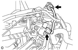


w/o EGR Cooler:
Disconnect the connector.
Disconnect the 2 vacuum hoses.
Remove the 2 bolts and electric vacuum regulating valve together with the bracket.
- NOTICE:
- Do not remove the electric vacuum regulating valve from the bracket.

| 8. REMOVE NO. 2 INTAKE AIR CONNECTOR BRACKET |
Remove the 3 bolts and No. 2 intake air connector bracket.
 |
| 9. REMOVE INTAKE AIR CONNECTOR |
Remove the 2 nuts, bolt, intake air connector and gasket.
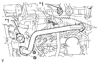
| 10. REMOVE NO. 1 EGR PIPE SUB-ASSEMBLY (w/ EGR System) |
Remove the 2 bolts, 2 nuts, No. 1 EGR pipe and 2 gaskets.
Text in Illustration *1 Gasket
 |
| 11. REMOVE ELECTRIC EGR CONTROL VALVE ASSEMBLY (w/ EGR System) |
w/ EGR Cooler:
Remove the 2 bolts, electric EGR control valve and gasket.

w/o EGR Cooler:
Disconnect the EGR valve position sensor connector.
Remove the electric EGR control valve and gasket.
| 12. REMOVE NO. 1, NO. 2 AND NO. 3 INJECTION PIPE SUB-ASSEMBLY |
- NOTICE:
- After removing the fuel pipe, cover the outlets on the common rail with tape to keep out foreign matter.
- After removing the fuel pipe, put it in a plastic bag to prevent foreign matter from contaminating its injector inlet.
w/ EGR Cooler:
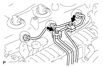
Remove the 2 nuts and No. 3 injection pipe clamp.
Remove the 2 bolts and 2 No. 2 injection pipe clamps.
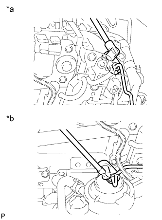
Using a 17 mm union nut wrench, loosen the union nuts and remove the No. 1, No. 2 and No. 3 injection pipes.
Text in Illustration *a Injector Side *b Common Rail Side

w/o EGR Cooler:
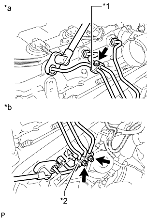
Remove the bolt and No. 2 injection pipe clamp.
Text in Illustration *1 No. 2 Injection Pipe Clamp *2 No. 3 Injection Pipe Clamp *a Injector Side *b Common Rail Side Remove the 2 nuts and No. 3 injection pipe clamp.
Using a 17 mm union nut wrench, loosen the union nuts and remove the No. 1, No. 2 and No. 3 injection pipes.
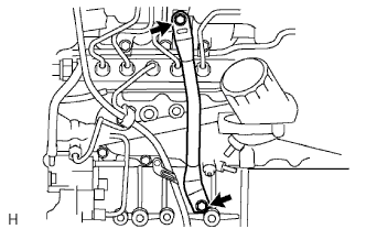
| 13. REMOVE NO. 4 INJECTION PIPE SUB-ASSEMBLY |
- NOTICE:
- If an injection pipe clamp is removed from the No. 4 injection pipe, replace the injection pipe clamp with a new one.
w/ EGR Cooler:
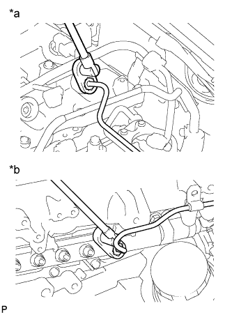
Remove the bolt and disconnect the injection pipe clamp.
Using a 17 mm union nut wrench, loosen the union nuts and remove the No. 4 injection pipe.
Text in Illustration *a Injector Side *b Common Rail Side

w/o EGR Cooler:
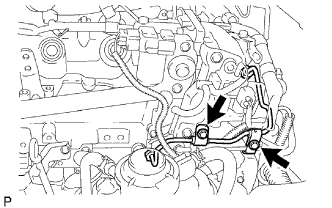
Remove the 2 bolts and disconnect the 2 injection pipe clamps.
Using a 17 mm union nut wrench, loosen the union nuts and remove the No. 4 injection pipe.
Text in Illustration *a Injector Side *b Common Rail Side
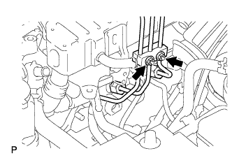
| 14. REMOVE NO. 2 NOZZLE LEAKAGE PIPE ASSEMBLY |
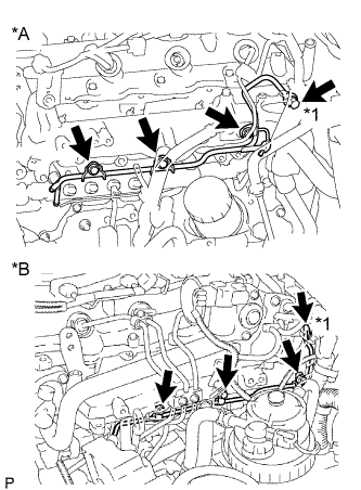
Disconnect the 3 fuel hoses.
Remove the union bolt, 3 bolts, No. 2 nozzle leakage pipe and gasket.
Text in Illustration *A w/ EGR Cooler *B w/o EGR Cooler *1 Union Bolt
 |
| 15. REMOVE INTAKE MANIFOLD |
 |
Remove the 2 nuts, 4 bolts, intake manifold and gasket.