Dtc P2772 Four Wheel Drive (4Wd) Low Switch Circuit Range / Performance
Drivetrain. Hilux. Tgn26, 36 Kun25, 26, 35, 36 Ggn25
DESCRIPTION
MONITOR DESCRIPTION
WIRING DIAGRAM
INSPECTION PROCEDURE
CHECK HARNESS AND CONNECTOR (NO. 1 TRANSFER INDICATOR SWITCH - BODY GROUND)
INSPECT NO. 1 TRANSFER INDICATOR SWITCH
CHECK HARNESS AND CONNECTOR (NO. 1 TRANSFER INDICATOR SWITCH - TCM)
DTC P2772 Four Wheel Drive (4WD) Low Switch Circuit Range / Performance |
DESCRIPTION
The TCM detects the signal from the No. 1 transfer indicator switch (the transfer L4 position switch).This DTC indicates that the No. 1 transfer indicator switch remains on.DTC No.
| DTC Detection Conditions
| Trouble Area
|
P2772
| The No. 1 transfer indicator switch remains on while the vehicle is being driven under the following conditions for 1.8 seconds or more (1 trip detection logic):
- Output shaft speed is between 750 and 3000 rpm.
- Transfer shift lever position is in H.
| - Short in No. 1 transfer indicator switch (the transfer L4 position switch) circuit
- No. 1 transfer indicator switch
- TCM
|
MONITOR DESCRIPTION
The TCM monitors the No. 1 transfer indicator switch to determine when the transfer-case L4 gear is engaged. If the transfer-case L4 gears remain engaged under all of the following conditions, the TCM will conclude that there is a malfunction of the No. 1 transfer indicator switch:- The No. 1 transfer indicator switch indicates that the L4 transfer-case gears are engaged.
- Transfer-case shift lever is in the "H" position.
- Transfer-case output shaft rpm is between 750 and 3000 rpm.
- The specified time period has elapsed.
Then the TCM will illuminate the MIL and store the DTC.
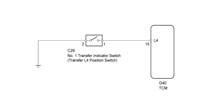
WIRING DIAGRAM
INSPECTION PROCEDURE
| 1.CHECK HARNESS AND CONNECTOR (NO. 1 TRANSFER INDICATOR SWITCH - BODY GROUND) |
Disconnect the No. 1 transfer indicator switch connector.
Measure the resistance according to the value(s) in the table below.
- Standard Resistance:
Tester Connection
| Condition
| Specified Condition
|
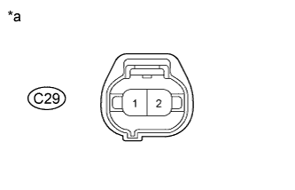
C29-2 - Body ground
| Always
| Below 1 Ω
|
Text in Illustration*a
| Front view of wire harness connector
(to No. 1 Transfer Indicator Switch)
|
| | REPAIR OR REPLACE HARNESS OR CONNECTOR |
|
|
| 2.INSPECT NO. 1 TRANSFER INDICATOR SWITCH |
Remove the No. 1 transfer indicator switch (HILUX_TGN26 RM00000479C00JX.html).
Measure the resistance according to the value(s) in the table below.
- Standard Resistance:
Tester Connection
| Switch Condition
| Specified Condition
|
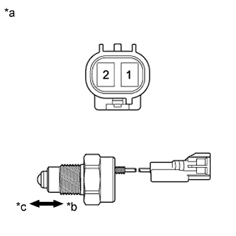
1 - 2
| Not pushed
| 10 kΩ or higher
|
1 - 2
| Pushed
| Below 1 Ω
|
Text in Illustration*a
| Component without harness connected
(No. 1 Transfer Indicator Switch)
|
*b
| Pushed
|
*c
| Not pushed
|
| 3.CHECK HARNESS AND CONNECTOR (NO. 1 TRANSFER INDICATOR SWITCH - TCM) |
Disconnect the C29 No. 1 transfer indicator switch connector.
Disconnect the G40 TCM connector.
Measure the resistance according to the value(s) in the table below.
- Standard Resistance:
Tester Connection
| Condition
| Specified Condition
|
C29-1 - G40-15 (L4)
| Always
| Below 1 Ω
|
C29-1 or G40-15 (L4) - Body ground
| Always
| 10 kΩ or higher
|
| | REPAIR OR REPLACE HARNESS OR CONNECTOR |
|
|