Dtc P0818 Driveline Disconnect Switch Input Circuit
Drivetrain. Hilux. Tgn26, 36 Kun25, 26, 35, 36 Ggn25
DESCRIPTION
MONITOR DESCRIPTION
WIRING DIAGRAM
INSPECTION PROCEDURE
CHECK HARNESS AND CONNECTOR (NO. 2 TRANSFER INDICATOR SWITCH - BODY GROUND)
INSPECT NO. 2 TRANSFER INDICATOR SWITCH (TRANSFER NEUTRAL POSITION SWITCH)
CHECK HARNESS AND CONNECTOR (NO. 2 TRANSFER INDICATOR SWITCH - ECM)
DTC P0818 Driveline Disconnect Switch Input Circuit |
DESCRIPTION
The ECM detects the signal from the transfer neutral position switch.This DTC indicates that the transfer neutral position switch remains on.DTC Code
| DTC Detection Condition
| Trouble Area
|
P0818
| Transfer neutral position switch remains on while vehicle is being driven under following conditions for 30 sec. (2-trip detection logic):
- Vehicle speed is 25 km/h (16 mph) or more
- Transfer shift lever is in H
| - Short in transfer neutral position switch circuit
- Transfer neutral position switch
- ECM
|
MONITOR DESCRIPTION
The ECM detects whether or not the transfer shift lever is in neutral by monitoring the signal from the transfer neutral position switch.If the transfer neutral position switch indicates that the transfer shift lever is in neutral under all of the following conditions, the ECM will conclude that there is a malfunction of the transfer neutral position switch.- The transfer shift lever is in the H position.
- The vehicle is traveling at 25 km/h (16 mph) or more.
- The transfer neutral position switch has been on for more than 30 seconds.
Then the ECM will illuminate the MIL and store the DTC.
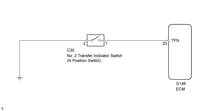
WIRING DIAGRAM
INSPECTION PROCEDURE
| 1.CHECK HARNESS AND CONNECTOR (NO. 2 TRANSFER INDICATOR SWITCH - BODY GROUND) |
Disconnect the C30 No. 2 transfer indicator switch connector.
Measure the resistance according to the value(s) in the table below.
- Standard Resistance:
Tester Connection
| Condition
| Specified Condition
|
C30-2 - Body ground
| Always
| Below 1 Ω
|
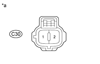
Text in Illustration*a
| Front view of wire harness connector
(to No. 2 Transfer Indicator Switch)
|
| | REPAIR OR REPLACE HARNESS OR CONNECTOR |
|
|
| 2.INSPECT NO. 2 TRANSFER INDICATOR SWITCH (TRANSFER NEUTRAL POSITION SWITCH) |
Remove the No. 2 transfer indicator switch.
Measure the resistance according to the value(s) in the table below.
- Standard Resistance:
Tester Connection
| Switch Condition
| Specified Condition
|
1 - 2
| Not pushed
| 10 kΩ or higher
|
1 - 2
| Pushed
| Below 1 Ω
|
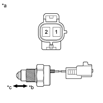
Text in Illustration*a
| Component without harness connected
(No. 2 Transfer Indicator Switch)
|
*b
| Pushed
|
*c
| Not pushed
|
| 3.CHECK HARNESS AND CONNECTOR (NO. 2 TRANSFER INDICATOR SWITCH - ECM) |
Disconnect the C30 No. 2 transfer indicator switch connector.
Disconnect the G146 ECM connector.
Measure the resistance according to the value(s) in the table below.
- Standard Resistance:
Tester Connection
| Condition
| Specified Condition
|
C30-1 - G146-23 (TFN)
| Always
| Below 1 Ω
|
C30-1 or G146-23 (TFN) - Body ground
| Always
| 10 kΩ or higher
|
| | REPAIR OR REPLACE HARNESS OR CONNECTOR |
|
|