DISCONNECT CABLE FROM NEGATIVE BATTERY TERMINAL (w/ Airbag System)
REMOVE AIR CONDITIONING DUCT SUB-ASSEMBLY (for Automatic Air Conditioning System)
Air Conditioning Unit -- Removal |
| 1. RECOVER REFRIGERANT FROM REFRIGERATION SYSTEM |
Start the engine.
Operate the cooler compressor under the conditions shown below:
This causes most of the compressor oil from the various components of the A/C system to collect in the A/C compressor.Item Condition Engine Speed Idling Operating Time 3 minutes or more A/C Switch Status On Blower Switch Status HI Set Temperature MAX COOL - NOTICE:
- It is not necessary to operate the cooler compressor if the A/C does not operate because of compressor lock, etc.
Stop the engine.
Recover the refrigerant from the A/C system using a refrigerant recovery unit.
- HINT:
- Use the refrigerant recovery unit in accordance with the manufacturer's instruction manual.
| 2. DISCONNECT ENGINE COOLANT |
for 1KD-FTV:
(HILUX_TGN26 RM000002SLF00QX_01_0001.html)
for 2KD-FTV:
(HILUX_TGN26 RM000002SLF00RX_01_0001.html)
for 2TR-FE:
(HILUX_TGN26 RM0000017H500NX_01_0001.html)
for 2TR-FBE:
(HILUX_TGN26 RM000003PS1007X_02_0001.html)
| 3. PRECAUTION (w/ Airbag System) |
- NOTICE:
- After turning the ignition switch off, waiting time may be required before disconnecting the cable from the battery terminal. Therefore, make sure to read the disconnecting the cable from the battery terminal notice before proceeding with work (HILUX_TGN26 RM000004QR1006X.html).
| 4. DISCONNECT CABLE FROM NEGATIVE BATTERY TERMINAL (w/ Airbag System) |
- CAUTION:
- Wait at least 90 seconds after disconnecting the cable from the negative (-) battery terminal to disable the SRS system.
- NOTICE:
- When disconnecting the cable, some systems need to be initialized after the cable is reconnected (HILUX_TGN26 RM000004QR3008X.html).
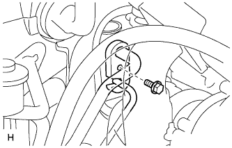
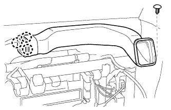
| 5. DISCONNECT SUCTION HOSE SUB-ASSEMBLY |
Remove the bolt and disconnect the suction hose sub-assembly.
- NOTICE:

- Do not use a screwdriver or similar tool to disconnect the suction hose sub-assembly.
- Seal the openings of the disconnected parts using vinyl tape to prevent moisture and foreign matter from entering.
Text in Illustration *a Disconnect tube by hand
 |
Remove the O-ring from the suction hose sub-assembly.
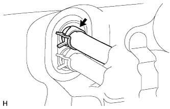
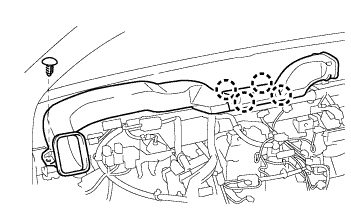
| 6. DISCONNECT AIR CONDITIONING TUBE AND ACCESSORY ASSEMBLY |
Disconnect the air conditioning tube and accessory assembly.
- NOTICE:
- Do not use a screwdriver or similar tool to disconnect the air conditioning tube and accessory assembly.
- Seal the openings of the disconnected parts using vinyl tape to prevent moisture and foreign matter from entering.
Remove the O-ring from the air conditioning tube and accessory assembly.
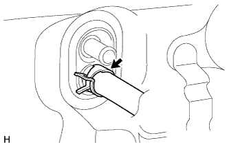
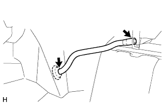
| 7. DISCONNECT HEATER WATER INLET HOSE |
 |
Using pliers, grip the claws of the clip and slide the clip to disconnect the heater water inlet hose.
- HINT:
- Collect the engine coolant in a container.
| 8. DISCONNECT HEATER WATER OUTLET HOSE |
 |
Using pliers, grip the claws of the clip and slide the clip to disconnect the heater water outlet hose.
- HINT:
- Collect the engine coolant in a container.
| 9. REMOVE UPPER INSTRUMENT PANEL SUB-ASSEMBLY |
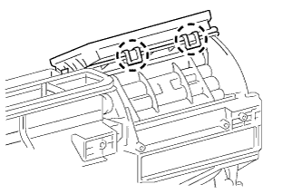
| 10. REMOVE NO. 2 HEATER TO REGISTER DUCT |
 |
Remove the 3 clips and No. 2 heater to register duct.
| 11. REMOVE NO. 1 HEATER TO REGISTER DUCT |
 |
Remove the clip.
Detach the 3 claws and remove the No. 1 heater to register duct.
| 12. REMOVE NO. 3 HEATER TO REGISTER DUCT |
 |
Remove the clip.
Detach the 4 claws and remove the No. 3 heater to register duct.
| 13. REMOVE DEFROSTER NOZZLE ASSEMBLY (w/ Defroster) |
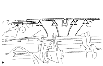 |
Using a screwdriver, detach the 4 clips and remove the defroster nozzle assembly.
| 14. REMOVE LOWER INSTRUMENT PANEL SUB-ASSEMBLY |
| 15. REMOVE STEERING COLUMN ASSEMBLY |
| 16. REMOVE NO. 1 AIR DUCT |
 |
Detach the 2 claws and remove the No. 1 air duct.
| 17. REMOVE NO. 2 AIR DUCT |
 |
Detach the 2 claws and remove the No. 2 air duct.
| 18. REMOVE NO. 4 AIR DUCT |
 |
Detach the 2 claws and remove the No. 4 air duct.
| 19. REMOVE NO. 1 INSTRUMENT PANEL BRACE SUB-ASSEMBLY |
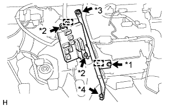 |
Detach the 2 clamps and remove the 2 nuts labeled A.
Disconnect the connectors and remove the driver side junction block.
Remove the screw.
Remove the bolt, nut labeled B and No. 1 instrument panel brace sub-assembly.
Text in Illustration *1 Screw *2 Nut A *3 Nut B *4 Bolt
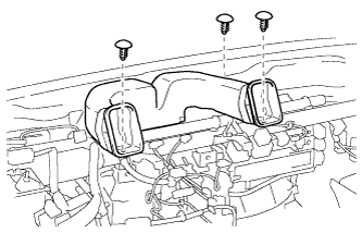
| 20. REMOVE AIR CONDITIONING DUCT SUB-ASSEMBLY (for Automatic Air Conditioning System) |
 |
Detach the 2 claws and remove the air conditioning duct sub-assembly.
| 21. REMOVE ECM |
for 1KD-FTV:
(HILUX_TGN26 RM0000013Z0019X.html)
for 2KD-FTV:
(HILUX_TGN26 RM0000043H100GX.html)
for 2TR-FE:
(HILUX_TGN26 RM000000VW202JX.html)
for 2TR-FBE:
(HILUX_TGN26 RM000000VW2024X.html)
| 22. REMOVE INSTRUMENT PANEL REINFORCEMENT |
Disconnect the connector and detach the 3 clamps.
 |
for Automatic Air Conditioning System:
Detach the clamp and disconnect the 2 connectors.
 |
for Manual Air Conditioning System:
Detach the clamp and disconnect the 2 connectors.
 |
Remove the 2 bolts and disconnect the ground wires from the instrument panel reinforcement.
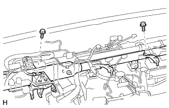 |
Remove the grommet from the vehicle body.
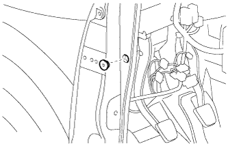 |
Detach the 12 clamps.
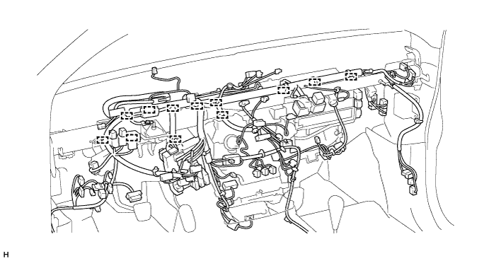
Disconnect the connectors.
Remove the 3 bolts.

for Automatic Transmission:
Remove the 7 bolts and instrument panel reinforcement.
for Manual Transmission:
Remove the 8 bolts and instrument panel reinforcement.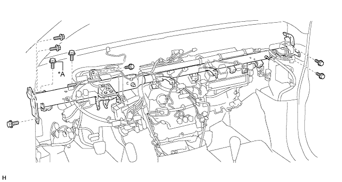
Text in Illustration *A for Manual Transmission - -
| 23. REMOVE NO. 1 COOLER UNIT DRAIN HOSE |
 |
Remove the No. 1 cooler unit drain hose.
| 24. REMOVE AIR CONDITIONING UNIT ASSEMBLY |
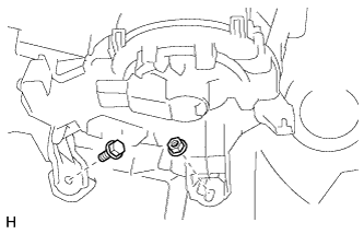 |
Remove the bolt, nut and air conditioning unit assembly.
| 25. REMOVE NO. 3 AIR DUCT |
 |
Detach the 2 claws and remove the No. 3 air duct.