Meter / Gauge System Tachometer Malfunction
DESCRIPTION
WIRING DIAGRAM
INSPECTION PROCEDURE
CHECK COMBINATION METER ASSEMBLY
CHECK ENGINE TYPE
CHECK HARNESS AND CONNECTOR (COMBINATION METER ASSEMBLY - ECM)
CHECK HARNESS AND CONNECTOR (COMBINATION METER ASSEMBLY - ECM)
METER / GAUGE SYSTEM - Tachometer Malfunction |
DESCRIPTION
In this circuit, the combination meter assembly receives engine speed signals from the ECM. The meter CPU displays the engine speed, which is calculated based on the data received from the ECM.
WIRING DIAGRAM
INSPECTION PROCEDURE
| 1.CHECK COMBINATION METER ASSEMBLY |
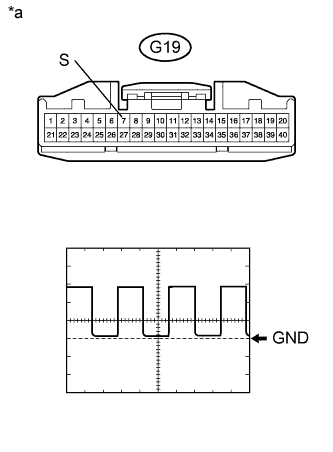
Disconnect the G19 combination meter assembly connector.
Using an oscilloscope, check the signal waveform of the meter.
Item
| Condition
|
Tester Connection
| G19-7 (S) - Body ground
|
Tool Setting
| 5 V/DIV., 10 msec./DIV.
|
Condition
| Engine idling
|
- HINT:
- As the engine speed increases, the wavelength shortens.
- OK:
- The waveform displayed is as shown in the illustration.
Text in Illustration*a
| Front view of wire harness connector
(to Combination Meter Assembly)
|
Check the engine type.
ResultResult
| Proceed to
|
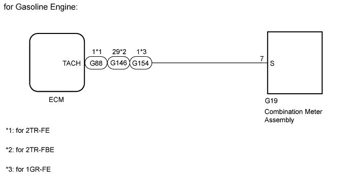
for Gasoline Engine
| A
|
for Diesel Engine
| B
|
| 3.CHECK HARNESS AND CONNECTOR (COMBINATION METER ASSEMBLY - ECM) |
Disconnect the G19 combination meter assembly connector.
Disconnect the G88*1, G146*2 or G154*3 ECM connector.
- *1: for 2TR-FE
- *2: for 2TR-FBE
- *3: for 1GR-FE
Measure the resistance according to the value(s) in the table below.
- Standard Resistance:
for 2TR-FETester Connection
| Condition
| Specified Condition
|
G19-7 (S) - G88-1 (TACH)
| Always
| Below 1 Ω
|
G19-7 (S) or G88-1 (TACH) - Body ground
| Always
| 10 kΩ or higher
|
for 2TR-FBETester Connection
| Condition
| Specified Condition
|
G19-7 (S) - G146-29 (TACH)
| Always
| Below 1 Ω
|
G19-7 (S) or G146-29 (TACH) - Body ground
| Always
| 10 kΩ or higher
|
for 1GR-FETester Connection
| Condition
| Specified Condition
|
G19-7 (S) - G154-1 (TACH)
| Always
| Below 1 Ω
|
G19-7 (S) or G154-1 (TACH) - Body ground
| Always
| 10 kΩ or higher
|
ResultResult
| Proceed to
|
NG
| A
|
OK
| B
|
- HINT:
- Refer to SFI system.
- SFI system (1GR-FE): HILUX_TGN26 RM000000PD90T9X.html
- SFI system (2TR-FE [w/o Secondary Air Injection System]): HILUX_TGN26 RM000000PD90TQX.html
- SFI system (2TR-FE [w/ Secondary Air Injection System]): HILUX_TGN26 RM000000PD90TRX.html
- SFI system (2TR-FBE): HILUX_TGN26 RM000000PD90QFX.html
| A |
|
|
|
| REPAIR OR REPLACE HARNESS AND CONNECTOR |
|
| 4.CHECK HARNESS AND CONNECTOR (COMBINATION METER ASSEMBLY - ECM) |
Disconnect the G19 combination meter assembly connector.
Disconnect the G39*1, G149*2 or G157*3 ECM connector.
- *1: for 1KD-FTV, 2KD-FTV
- *2: for 1KD-FTV, 2KD-FTV (for DPF)
- *3: for 1KD-FTV (for i-ART)
Measure the resistance according to the value(s) in the table below.
- Standard Resistance:
for 1KD-FTV, 2KD-FTVTester Connection
| Condition
| Specified Condition
|
G19-7 (S) - G39-4 (TACH)
| Always
| Below 1 Ω
|
G19-7 (S) or G39-4 (TACH) - Body ground
| Always
| 10 kΩ or higher
|
for 1KD-FTV, 2KD-FTV (for DPF)Tester Connection
| Condition
| Specified Condition
|
G19-7 (S) - G149-18 (TACH)
| Always
| Below 1 Ω
|
G19-7 (S) or G149-18 (TACH) - Body ground
| Always
| 10 kΩ or higher
|
for 1KD-FTV (for i-ART)Tester Connection
| Condition
| Specified Condition
|
G19-7 (S) - G157-18 (TACH)
| Always
| Below 1 Ω
|
G19-7 (S) or G157-18 (TACH) - Body ground
| Always
| 10 kΩ or higher
|
ResultResult
| Proceed to
|
NG
| A
|
OK
| B
|
- HINT:
- Refer to ECD system.
- ECD system (1KD-FTV [for DPF]): HILUX_TGN26 RM0000012WB04PX.html
- ECD system (1KD-FTV [for i-ART]): HILUX_TGN26 RM0000012WB04RX.html
- ECD system (1KD-FTV [w/o EGR Cooler]): HILUX_TGN26 RM0000012WB04TX.html
- ECD system (1KD-FTV [w/ EGR Cooler]): HILUX_TGN26 RM0000012WB04SX.html
- ECD system (2KD-FTV [for DPF]): HILUX_TGN26 RM0000012WB04QX.html
- ECD system (2KD-FTV [w/o EGR Cooler]): HILUX_TGN26 RM0000012WB04VX.html
- ECD system (2KD-FTV [w/ EGR Cooler]): HILUX_TGN26 RM0000012WB04UX.html
| A |
|
|
|
| REPAIR OR REPLACE HARNESS OR CONNECTOR |
|