Load Sensing Proportioning Valve (W/O Vsc) -- Installation |
| 1. INSTALL LOAD SENSING SPRING BUSH & BOOT KIT |
Install the load sensing valve boot and load sensing spring boot to the spring.
Install the 2 dust seals, 2 collars and 2 No. 1 load sensing spring bushes and 2 No. 2 load sensing spring bushes to the load sensing spring assembly.
- NOTICE:
- Apply lithium soap base glycol grease to all contact surfaces.
- Make sure the valve side and shackle side of the spring are installed properly.
| 2. INSTALL NO. 1 AND NO. 2 SHACKLES |
Install the adjusting nut and No. 2 shackle to the No. 1 shackle.
Tighten the lock nut.
- Torque:
- 13 N*m{127 kgf*cm, 9 ft.*lbf}
Install the No. 1 shackle (with the No. 2 shackle) to the spring.
Install the 2 plate washers and spring washer with the bolt and nut.
- Torque:
- 18 N*m{184 kgf*cm, 13 ft.*lbf}
| 3. INSTALL LOAD SENSING SPRING ASSEMBLY |
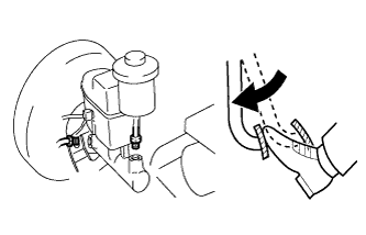
Using pliers, install the spring to the valve body with the clip.
| 4. INSTALL LOAD SENSING VALVE BRACKET |
Install the load sensing valve bracket to the valve with the nut and bolt.
- Torque:
- 18 N*m{184 kgf*cm, 13 ft.*lbf}
| 5. INSTALL REAR FLEXIBLE HOSE BRACKET |
Install the bracket and valve set plate to the valve 2 spring washer with the 2 nuts.
- Torque:
- 13 N*m{127 kgf*cm, 9 ft.*lbf}
Install a new clip.
Using a union nut wench, connect the No. 6 brake tube to the rear brake flexible hose.
- Torque:
- 15 N*m{155 kgf*cm, 11 ft.*lbf}
- NOTICE:
- Use the formula to calculate special torque values for situations where a union nut wrench is combined with a torque wrench (HILUX_TGN26 RM000004QR1006X.html).
| 6. INSTALL LOAD SENSING PROPORTIONING VALVE ASSEMBLY |
Install the valve with the 3 bolts.
- Torque:
- 29 N*m{300 kgf*cm, 22 ft.*lbf}
Using a union nut wrench, connect the 3 brake lines to the valve body.
- Torque:
- 15 N*m{155 kgf*cm, 11 ft.*lbf}
- NOTICE:
- Use the formula to calculate special torque values for situations where a union nut wrench is combined with a torque wrench (HILUX_TGN26 RM000004QR1006X.html).
| 7. CONNECT NO. 2 LOAD SENSING SPRING SHACKLE |
Connect the No. 2 shackle to the rear differential.
Install the bolt, collar and 2 load sensing valve bushes.
- Torque:
- 29 N*m{300 kgf*cm, 22 ft.*lbf}
| 8. BLEED BRAKE SYSTEM (for TASA Made) |
Bleed the brake master cylinder.
Remove the brake master cylinder reservoir filler cap assembly.
Add brake fluid to keep the level between the MIN and MAX lines of the reservoir while bleeding the brakes.
- Fluid:
- SAE J1709 or FMVSS No. 116 DOT 3
Using a union nut wrench, disconnect the 2 brake tubes from the master cylinder.
Slowly depress and hold the brake pedal.
Block the tube holes with your fingers, and then release the brake pedal.
Remove your fingers, slowly depress and hold the brake pedal, block the tube holes with your fingers again, and then release the brake pedal. Repeat this step 3 or 4 times.
Using a union nut wrench, connect the 2 brake tubes to the brake master cylinder assembly.
- Torque:
- 15 N*m{155 kgf*cm, 11 ft.*lbf}
- NOTICE:
- Use the formula to calculate special torque values for situations where a union nut wrench is combined with a torque wrench (HILUX_TGN26 RM000004QR1006X.html).


Bleed the load sensing proportioning valve.
Remove the bleeder plug cap.
Connect a vinyl tube to the bleeder plug.
Depress the pedal several times, and then loosen the bleeder plug with the pedal depressed.
When fluid stops coming out, immediately tighten the bleeder plug. Then release the pedal.
Repeat the 2 previous steps until all the air in the brake fluid is gone.
Tighten the bleeder plug.
- Torque:
- 11 N*m{107 kgf*cm, 8 ft.*lbf}
Install the bleeder plug cap.
Bleed the brake line.
Remove the bleeder plug cap.
Connect a vinyl tube to the bleeder plug.
Depress the brake pedal several times, and then loosen the bleeder plug with the pedal depressed.*1
When fluid stops coming out, tighten the bleeder plug, and then release the brake pedal.*2
Repeat *1 and *2 until all the air in the fluid is completely bled out.
Tighten the bleeder plug completely.
- Torque:
- for Front Brake:
- 11 N*m{110 kgf*cm, 8 ft.*lbf}
- for Rear Brake:
- 10 N*m{102 kgf*cm, 7 ft.*lbf}
Repeat the above procedure for each wheel to bleed the brake line.
Install the bleeder plug cap.
Check for brake fluid leaks.
Check the brake fluid level in the reservoir (HILUX_TGN26 RM0000010K4010X_01_0001.html).
| 9. BLEED BRAKE SYSTEM (for TMT Made) |
Bleed the brake master cylinder.
Remove the brake master cylinder reservoir filler cap assembly.
Add brake fluid to keep the level between the MIN and MAX lines of the reservoir while bleeding the brakes.
- Fluid:
- SAE J1703 or FMVSS No. 116 DOT 3
Using a union nut wrench, disconnect the 2 brake tubes from the master cylinder.
Slowly depress and hold the brake pedal.
Block the tube holes with your fingers, and then release the brake pedal.
Remove your fingers, slowly depress and hold the brake pedal, block the tube holes with your fingers again, and then release the brake pedal. Repeat this step 3 or 4 times.
Using a union nut wrench, connect the 2 brake tubes to the brake master cylinder assembly.
- Torque:
- 15 N*m{155 kgf*cm, 11 ft.*lbf}
- NOTICE:
- Use the formula to calculate special torque values for situations where a union nut wrench is combined with a torque wrench (HILUX_TGN26 RM000004QR1006X.html).

Bleed the load sensing proportioning valve.
Remove the bleeder plug cap.
Connect a vinyl tube to the bleeder plug.
Depress the pedal several times, and then loosen the bleeder plug with the pedal depressed.
When fluid stops coming out, immediately tighten the bleeder plug. Then release the pedal.
Repeat the 2 previous steps until all the air in the brake fluid is gone.
Tighten the bleeder plug.
- Torque:
- 11 N*m{107 kgf*cm, 8 ft.*lbf}
Install the bleeder plug cap.
Bleed the brake line.
Remove the bleeder plug cap.
Connect a vinyl tube to the bleeder plug.
Depress the brake pedal several times, and then loosen the bleeder plug with the pedal depressed.*1
When fluid stops coming out, tighten the bleeder plug, and then release the brake pedal.*2
Repeat *1 and *2 until all the air in the fluid is completely bled out.
Tighten the bleeder plug completely.
- Torque:
- for Front Brake:
- 11 N*m{110 kgf*cm, 8 ft.*lbf}
- for Rear Brake:
- 10 N*m{102 kgf*cm, 7 ft.*lbf}
Repeat the above procedure for each wheel to bleed the brake line.
Install the bleeder plug cap.
Check for brake fluid leaks.
Check the brake fluid level in the reservoir (HILUX_TGN26 RM0000010K400VX_01_0001.html).
| 10. BLEED BRAKE SYSTEM (for TDV Made) |
Bleed the brake master cylinder.
Remove the brake master cylinder reservoir filler cap assembly.
Add brake fluid to keep the level between the MIN and MAX lines of the reservoir while bleeding the brakes.
- Fluid:
- SAE J1703 or FMVSS No. 116 DOT 3
Using a union nut wrench, disconnect the 2 brake tubes from the master cylinder.
Slowly depress and hold the brake pedal.
Block the tube holes with your fingers, and then release the brake pedal.
Remove your fingers, slowly depress and hold the brake pedal, block the tube holes with your fingers again, and then release the brake pedal. Repeat this step 3 or 4 times.
Using a union nut wrench, connect the 2 brake tubes to the brake master cylinder assembly.
- Torque:
- 15 N*m{155 kgf*cm, 11 ft.*lbf}
- NOTICE:
- Use the formula to calculate special torque values for situations where a union nut wrench is combined with a torque wrench (HILUX_TGN26 RM000004QR1006X.html).
Bleed the load sensing proportioning valve.
Remove the bleeder plug cap.
Connect a vinyl tube to the bleeder plug.
Depress the pedal several times, and then loosen the bleeder plug with the pedal depressed.
When fluid stops coming out, immediately tighten the bleeder plug. Then release the pedal.
Repeat the 2 previous steps until all the air in the brake fluid is gone.
Tighten the bleeder plug.
- Torque:
- 11 N*m{107 kgf*cm, 8 ft.*lbf}
Install the bleeder plug cap.
Bleed the brake line.
Remove the bleeder plug cap.
Connect a vinyl tube to the bleeder plug.
Depress the brake pedal several times, and then loosen the bleeder plug with the pedal depressed.*1
When fluid stops coming out, tighten the bleeder plug, and then release the brake pedal.*2
Repeat *1 and *2 until all the air in the fluid is completely bled out.
Tighten the bleeder plug completely.
- Torque:
- for Front Brake:
- 11 N*m{110 kgf*cm, 8 ft.*lbf}
- for Rear Brake:
- 10 N*m{102 kgf*cm, 7 ft.*lbf}
Repeat the above procedure for each wheel to bleed the brake line.
Install the bleeder plug cap.
Check for brake fluid leaks.
Check the brake fluid level in the reservoir (HILUX_TGN26 RM0000010K4018X_01_0001.html).
| 11. BLEED BRAKE SYSTEM (for TSAM Made) |
Bleed the brake master cylinder.
Remove the brake master cylinder reservoir filler cap assembly.
Add brake fluid to keep the level between the MIN and MAX lines of the reservoir while bleeding the brakes.
- Fluid:
- SAE J1704 or FMVSS No. 116 DOT 4
Using a union nut wrench, disconnect the 2 brake tubes from the master cylinder.
Slowly depress and hold the brake pedal.
Block the tube holes with your fingers, and then release the brake pedal.
Remove your fingers, slowly depress and hold the brake pedal, block the tube holes with your fingers again, and then release the brake pedal. Repeat this step 3 or 4 times.
Using a union nut wrench, connect the 2 brake tubes to the brake master cylinder assembly.
- Torque:
- 15 N*m{155 kgf*cm, 11 ft.*lbf}
- NOTICE:
- Use the formula to calculate special torque values for situations where a union nut wrench is combined with a torque wrench (HILUX_TGN26 RM000004QR1006X.html).
Bleed the load sensing proportioning valve.
Remove the bleeder plug cap.
Connect a vinyl tube to the bleeder plug.
Depress the pedal several times, and then loosen the bleeder plug with the pedal depressed.
When fluid stops coming out, immediately tighten the bleeder plug. Then release the pedal.
Repeat the 2 previous steps until all the air in the brake fluid is gone.
Tighten the bleeder plug.
- Torque:
- 11 N*m{107 kgf*cm, 8 ft.*lbf}
Install the bleeder plug cap.
Bleed the brake line.
Remove the bleeder plug cap.
Connect a vinyl tube to the bleeder plug.
Depress the brake pedal several times, and then loosen the bleeder plug with the pedal depressed.*1
When fluid stops coming out, tighten the bleeder plug, and then release the brake pedal.*2
Repeat *1 and *2 until all the air in the fluid is completely bled out.
Tighten the bleeder plug completely.
- Torque:
- for Front Brake:
- 11 N*m{110 kgf*cm, 8 ft.*lbf}
- for Rear Brake:
- 10 N*m{102 kgf*cm, 7 ft.*lbf}
Repeat the above procedure for each wheel to bleed the brake line.
Install the bleeder plug cap.
Check for brake fluid leaks.
Check the brake fluid level in the reservoir (HILUX_TGN26 RM0000010K4019X_01_0001.html).
| 12. BLEED CLUTCH LINE (for Manual Transmission) |
Remove the bleeder plug cap of the release cylinder.
Connect a vinyl tube to the bleeder plug.
Depress the clutch pedal several times, and then loosen the bleeder plug while the pedal is depressed.
When fluid no longer comes out, tighten the bleeder plug, and then release the clutch pedal.
Repeat the previous 2 steps until all the air in the fluid is completely bled.
Tighten the bleeder plug.
- Torque:
- 11 N*m{110 kgf*cm, 8 ft.*lbf}
Install the bleeder plug cap.
Check that all the air has been bled from the clutch line.
| 13. CHECK LOAD SENSING PROPORTIONING VALVE ASSEMBLY |
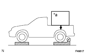 |
| *a | Weight |
Set the vehicle to its curb weight.
Place weights (as necessary) on the rear deck until the rear axle load is as shown below.
- Standard Rear Axle Load:
Vehicle Type Specified condition except 1GR-FE 9807 N (1000 kgf, 2205 lbf) for 1GR-FE 10297 N (1050 kgf, 2315 lbf)
- NOTICE:
- Be sure that the vehicle is on a level surface before starting the procedure.
- After placing approximately 60 kg (132 lb) more than the set value, remove weights slowly as necessary so that the load is within +/-15 kg (33 lb) of the adjusted value and there is less than a 25 kg (55 lb) difference between the right and left sides.
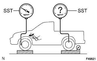
Install SST and bleed air from the brake system.
- SST
- 09709-29018
 |
Raise the front brake fluid pressure to 10000 kPa (107.6 kgf/cm2, 1450 psi) by depressing the brake pedal, and measure the rear brake fluid pressure.
- Standard Rear Brake Fluid Pressure:
- 4450 +/-490 kPa (45.4 +/-5.0 kgf/cm2, 645 +/-71 psi)
- HINT:
- The pedal should not be depressed twice or released while raising the front brake fluid pressure.
- Read the value of the rear brake fluid pressure after raising and holding the front fluid pressure for 2 seconds.
 |
| 14. ADJUST LOAD SENSING PROPORTIONING VALVE ASSEMBLY |
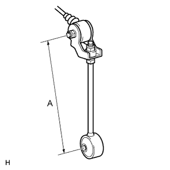
Adjust the length of the No. 2 load sensing spring shackle.
When the rear brake fluid pressure is below the standard pressure, lengthen length A.
When the rear brake fluid pressure is higher than the standard pressure, shorten length A.- Standard Initial Length (A):
- 190 mm (7.543 in.)
- Standard Length (A) after Adjustment:
- 184 to 196 mm (7.305 to 7.781 in.)
- HINT:
- The rear brake fluid pressure changes according to the table below by adjusting length A.
- Standard Pressure Change:
- Changes by 120 kPa (1.2 kgf/cm2, 17.6 psi) for every 1 mm (0.0394 in.) change in length A
 |
If the pressure cannot be adjusted by the No. 2 load sensing spring shackle, loosen the nuts and raise or lower the valve body.
When the pressure is below the standard pressure, lower the load sensing valve assembly.
When the pressure is higher than the standard pressure, raise the load sensing valve assembly.
 |
Tighten the nuts.
- Torque:
- 13 N*m{127 kgf*cm, 9 ft.*lbf}
Adjust the length of the No. 2 load sensing spring shackle again.
- HINT:
- If the length cannot be adjusted, check the load sensing valve assembly.