Front Propeller Shaft Assembly (For Tmt Made) -- Reassembly |
- NOTICE:
- When using a vise, place aluminum plates between the part and vise.
- When using a vise, do not overtighten it.
| 1. INSTALL UNIVERSAL JOINT SPIDER ASSEMBLY |
 |
- HINT:
- Use the same procedure for both universal joint spiders.
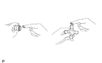
Apply MP grease to a new spider and 2 new spider bearings.
- NOTICE:
- Be careful not to apply too much grease.
Fit the spider into the flange yoke.
Using SST, install the 2 spider bearings to the spider.
- SST
- 09332-25010
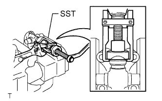 |
Using SST, adjust the spider bearings so that: 1) the flange yoke does not overlap the snap ring grooves of the spider bearings; 2) the grooves are as wide as possible; and 3) the groove width on both sides is the same.
- SST
- 09332-25010
 |
Install 2 new snap rings to the installed spider bearings. The snap rings must have equal thickness and allow 0 to 0.05 mm (0 to 0.00196 in.) of axial play.
- Standard Snap Ring Thickness :
Part No. Thickness Mark 90520-T0007 2.19 mm (0.0862 in.) F 90520-T0008 2.21 mm (0.0870 in.) G 90520-T0009 2.23 mm (0.0878 in.) H 90520-T0010 2.25 mm (0.0886 in.) J 90520-T0011 2.27 mm (0.0894 in.) K 90520-T0012 2.29 mm (0.0902 in.) 1 90520-T0013 2.31 mm (0.0909 in.) 2 90520-T0014 2.33 mm (0.0917 in.) 3 90520-T0015 2.35 mm (0.0925 in.) 4 90520-T0016 2.37 mm (0.0933 in.) 5 90520-T0017 2.39 mm (0.0941 in.) 6 90520-T0018 2.41 mm (0.0949 in.) 7 90520-T0019 2.43 mm (0.0957 in.) 8 90520-T0020 2.45 mm (0.0965 in.) N 90520-T0021 2.47 mm (0.0972 in.) 10 90520-T0022 2.49 mm (0.0980 in.) A 90520-T0023 2.51 mm (0.0988 in.) B 90520-T0024 2.53 mm (0.0996 in.) C 90520-T0025 2.55 mm (0.1004 in.) D 90520-T0026 2.57 mm (0.1012 in.) E
- NOTICE:
- New snap rings must be used.
- The snap ring thickness must be the same on both ends.
Using a plastic-faced hammer, tap the flange yoke until there is no clearance between the spider bearings and snap rings.
Text in Illustration *a Hammering Point
 |
Align the matchmarks on the flange yoke and propeller shaft.
Install new spider bearings on the sleeve yoke side.
- HINT:
- Use the procedure described above.
| 2. INSPECT UNIVERSAL JOINT SPIDER ASSEMBLY |
Clamp the propeller shaft in a vise between aluminum plates.
- NOTICE:
- Do not overtighten the vise.
Check the spider bearings for wear or damage.
Check the axial play of each spider bearing by turning the yoke while holding the shaft tightly.
- Maximum bearing axial play:
- 0.05 mm (0.00196 in.)
 |
| 3. INSPECT PROPELLER SHAFT GREASE FITTING DIRECTION |
- HINT:
- When replacing a spider bearing, be sure that the grease fitting hole is facing the direction shown in the illustration.
- Fill the grease fittings with MP grease.
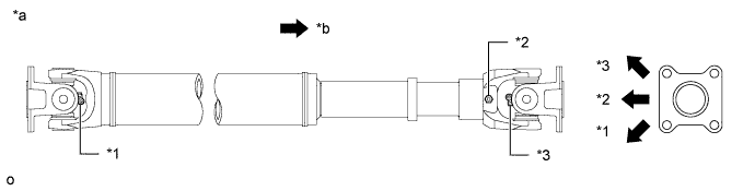
| *1 | No. 1 Grease Fitting | *2 | No. 2 Grease Fitting |
| *3 | No. 3 Grease Fitting | - | - |
| *a | Spider grease fitting assembly direction for front propeller shaft assembly | *b | Rear Side |