Engine Assembly -- Removal |
| 1. DISCHARGE FUEL SYSTEM PRESSURE |
| 2. PRECAUTION |
- NOTICE:
- After turning the ignition switch off, waiting time may be required before disconnecting the cable from the battery terminal. Therefore, make sure to read the disconnecting the cable from the battery terminal notice before proceeding with work (HILUX_TGN26 RM000004QR1006X.html).
| 3. DISCONNECT CABLE FROM NEGATIVE BATTERY TERMINAL |
- NOTICE:
- When disconnecting the cable, some systems need to be initialized after the cable is reconnected (HILUX_TGN26 RM000004QR300CX.html).
| 4. DRAIN ENGINE COOLANT |
- CAUTION:
- Do not remove the radiator cap while the engine and radiator are still hot. Pressurized, hot engine coolant and steam may be released and cause serious burns.

Text in Illustration *1 Radiator Cap *2 Reservoir Cap *3 Cylinder Block Water Drain Cock Plug *4 Reservoir Tank *5 Radiator Drain Cock Plug - -
Loosen the radiator drain cock plug.
Remove the radiator cap and drain the coolant.
- HINT:
- Collect the coolant in a container and dispose of it according to the regulations in your area.
Loosen the cylinder block water drain cock plug and drain the coolant from the engine.
| 5. DRAIN ENGINE OIL |
Remove the oil filler cap.
Remove the oil drain plug, and drain the engine oil from the oil pan.
- NOTICE:
- Collect the oil in an oil disposal container.
Wipe the oil pan and drain plug.
Install a new gasket and the drain plug.
- Torque:
- 40 N*m{408 kgf*cm, 30 ft.*lbf}
| 6. REMOVE HOOD SUB-ASSEMBLY |
Disconnect the washer nozzle hose.
Remove the 4 bolts and hood.
| 7. REMOVE ENGINE SIDE COVER SUB-ASSEMBLY LH |
Remove the 2 clips, 3 bolts and engine side cover.
 |
| 8. REMOVE ENGINE SIDE COVER SUB-ASSEMBLY RH |
- HINT:
- Use the same procedure described for the LH side.
| 9. REMOVE NO. 1 ENGINE UNDER COVER |
| 10. REMOVE NO. 2 ENGINE UNDER COVER |
Remove the 4 bolts and No. 2 engine under cover.
| 11. REMOVE V-BANK COVER |
Remove the 2 nuts and V-bank cover.
 |
| 12. DISCONNECT NO. 2 PCV HOSE |
Disconnect the clamp and No. 2 PCV hose.
 |
| 13. REMOVE AIR CLEANER ASSEMBLY |
Disconnect the vacuum hose.
 |
Disconnect the mass air flow meter connector.
Detach the 2 wire harness clamps.
Loosen the 2 hose clamps.
 |
Remove the 2 bolts and air cleaner.
| 14. REMOVE NO. 2 AIR CLEANER HOSE |
Remove the 2 bolts and No. 2 air cleaner hose.
| 15. REMOVE RADIATOR GRILLE |
Put protective tape around the radiator grille.
Text in Illustration *1 Protective Tape
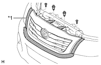 |
Remove the 2 clips and 2 screws.
Detach the 6 claws and remove the radiator grille.
 |
| 16. REMOVE RADIATOR SIDE DEFLECTOR RH |
Using a clip remover, remove the 2 clips.
Detach the claw and remove the deflector.
| 17. REMOVE RADIATOR SIDE DEFLECTOR LH |
Using a clip remover, remove the 2 clips.
Detach the claw and remove the deflector.
| 18. REMOVE RADIATOR HOSE INLET |
| 19. REMOVE RADIATOR HOSE OUTLET |
| 20. DISCONNECT OIL COOLER INLET HOSE |
Disconnect the oil cooler inlet hose from radiator tank lower.
| 21. DISCONNECT OIL COOLER OUTLET HOSE |
Disconnect the oil cooler outlet hose from radiator tank lower.
| 22. REMOVE FAN SHROUD |
Remove the 3 bolts and oil reservoir.
 |
Disconnect the reservoir hose from the radiator tank upper.
Loosen the 4 nuts holding the fluid coupling fan.
Remove the fan and generator V belt (HILUX_TGN26 RM000000YN400BX_01_0001.html).
Remove the 2 bolts holding the fan shroud.
Remove the 4 nuts of the fluid coupling fan, and then remove the shroud together with the fluid coupling fan.
- NOTICE:
- Be careful not to damage the radiator core.
Remove the fan pulley from the water pump.
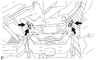
| 23. REMOVE RADIATOR ASSEMBLY |
Disconnect the 2 front airbag sensor connectors.
Using a clip remover, detach the 4 clamps from the radiator side as shown in the illustration.
- HINT:
- Tape the clip remover tip before use.
 |
Remove the 4 bolts and radiator assembly.
 |
| 24. DISCONNECT VANE PUMP ASSEMBLY |
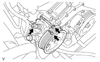 |
Disconnect the power steering oil pressure switch connector.
Remove the 2 bolts and disconnect the vane pump.
- NOTICE:
- Do not hit other parts with the pulley when disconnecting the vane pump.
- HINT:
- Make sure to suspend the vane pump securely.
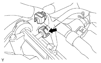
| 25. DISCONNECT COOLER COMPRESSOR ASSEMBLY |
Remove the 2 bolts and disconnect the suction hose from the engine.
 |
Disconnect the cooler compressor connector.
 |
Remove the 4 bolts and disconnect the compressor from the engine.
Support the cooler compressor securely.
| 26. DISCONNECT NO. 1 FUEL PIPE SUB-ASSEMBLY |
Disconnect the No. 1 fuel pipe (HILUX_TGN26 RM000000YL401PX.html).
 |
| 27. DISCONNECT NO. 2 FUEL PIPE SUB-ASSEMBLY |
Disconnect the No. 2 fuel pipe (HILUX_TGN26 RM000000YL401PX.html).
 |
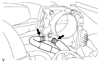
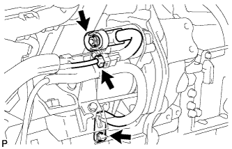
| 28. DISCONNECT HEATER WATER HOSE |
Disconnect the heater water inlet hose.
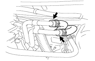 |
Disconnect the heater water outlet hose.
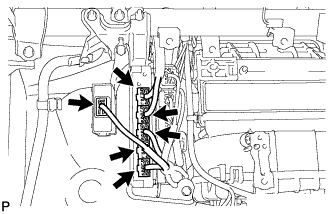
| 29. REMOVE INTAKE AIR SURGE TANK |
Disconnect the No. 4 water by-pass hose.
 |
Disconnect the No. 5 water by-pass hose.
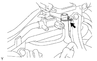
Disconnect the purge line hose.
 |
Disconnect the vacuum hose.
Disconnect the No. 1 PCV hose.
 |
Disconnect the purge VSV connector.
 |
Disconnect the vacuum switching valve (for ACIS) connector.
Disconnect the throttle body connector.
Detach the 3 wire harness clamps and disconnect the wire harness.
Remove the 2 bolts and throttle body bracket.
 |
Remove the bolt and oil baffle plate.
 |
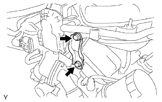
Remove the 2 bolts and No. 1 surge tank stay.
Remove the 2 bolts and No. 2 surge tank stay.
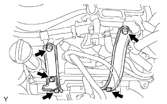
Remove the 2 bolts and disconnect the water hose sub-assembly.
 |
Using an 8 mm hexagon wrench, remove the 4 bolts, 2 nuts, intake air surge tank and gasket.
Text in Illustration 
Bolt 
Nut
 |
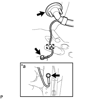
| 30. DISCONNECT ENGINE WIRE |
 |
Disconnect the ECM connectors from the cabin
Remove the glove compartment door (HILUX_TGN26 RM000003O1000VX_02_0011.html).
Disconnect the 4 ECM connectors.
Disconnect the 4 wheel drive control ECU connector.
Remove the bolt and clamp, and disconnect the ground wire.
Text in Illustration *a Frame Side
 |
Remove the bolt and disconnect the ground wire from the frame.
Pull out the engine wire from the cabin.
Remove the upper relay block cover.
Remove the side relay block cover.
Using a screwdriver, detach the 4 claws and remove the relay block cover.
Text in Illustration *a Pull - HINT:
- Tape the screwdriver tip before use.
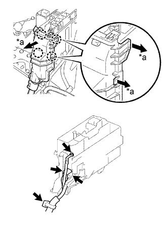 |
Remove the nut and disconnect the cable from the engine room junction block.
Disconnect the 2 engine room junction block connectors and detach the wire clamp.
Remove the bolt and detach the wire clamp from the front No. 1 engine mounting bracket LH.
Disconnect the differential actuator connector.
| 31. DISCONNECT NO. 2 ENGINE WIRE |
Remove the bolt and disconnect the No. 2 engine wire from the cylinder block.
 |
| 32. REMOVE BATTERY |
| 33. REMOVE FRONT NO. 2 EXHAUST PIPE ASSEMBLY |
Remove the 2 bolts and 4 nuts.
Disconnect the exhaust pipe support and remove the front No. 2 exhaust pipe.
Remove the 2 gaskets.
| 34. REMOVE FRONT EXHAUST PIPE ASSEMBLY |
Remove the 2 bolts, 2 compression springs and 2 nuts.
Disconnect the exhaust pipe support and remove the front exhaust pipe.
Remove the 2 gaskets.
| 35. REMOVE FRONT FENDER SEAL |
Remove the 10 clips and RH and LH fender seals.
| 36. REMOVE FRONT FENDER APRON SEAL UPPER |
Remove the 10 clips and RH and LH fender apron seals.
| 37. REMOVE MANIFOLD STAY |
Remove the 3 bolts and manifold stay.
| 38. REMOVE EXHAUST MANIFOLD SUB-ASSEMBLY RH |
Disconnect the air fuel ratio sensor connector.
Remove the 6 nuts, exhaust manifold and gasket.
 |
| 39. REMOVE NO. 2 MANIFOLD STAY |
Remove the 3 bolts and No. 2 manifold stay.
| 40. REMOVE EXHAUST MANIFOLD SUB-ASSEMBLY LH |
Disconnect the air fuel ratio sensor connector.
Remove the 6 nuts, exhaust manifold and gasket.
 |
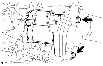
| 41. REMOVE STARTER ASSEMBLY |
 |
Disconnect the starter connector.
Disconnect the terminal cap.
Remove the nut and disconnect the starter wire.
Remove the bolt and disconnect the wire harness.
Remove the 2 bolts and starter.
 |
| 42. REMOVE AUTOMATIC TRANSMISSION ASSEMBLY |
| 43. REMOVE REAR NO. 1 ENGINE MOUNTING INSULATOR |
 |
Remove the 4 bolts and rear No. 1 engine mounting insulator from the automatic transmission.
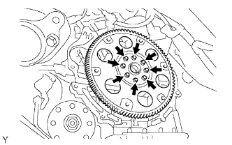
| 44. REMOVE DRIVE PLATE AND RING GEAR SUB-ASSEMBLY |
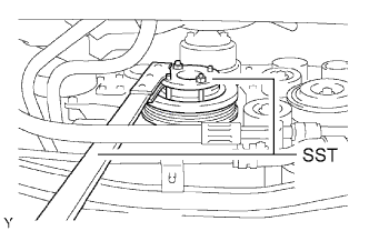 |
Using SST, hold the crankshaft.
- SST
- 09213-54015(91651-60855)
09330-00021
Remove the 8 bolts, rear spacer, drive plate and ring gear and front spacer.
- NOTICE:
- Do not reuse the bolts.
 |
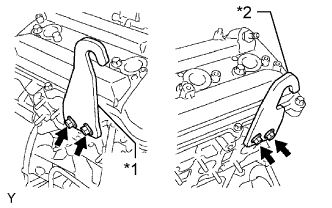
| 45. INSTALL ENGINE HANGER |
Install the 2 engine hangers with 4 bolts as shown in the illustration.
- Torque:
- 33 N*m{337 kgf*cm, 24 ft.*lbf}
Text in Illustration *1 No. 1 Engine Hanger *2 No. 2 Engine Hanger - HINT:
No. 1 Engine Hanger 12281-31060 No. 2 Engine Hanger 12282-31040 Bolt 90119-08A87
 |
| 46. REMOVE ENGINE ASSEMBLY |
Attach an engine sling device and hang the engine with a chain block.
Remove the 4 bolts and 4 nuts holding the engine mounting brackets to the frame.
 |
Lift the engine out of the vehicle carefully.
- NOTICE:
- Make sure the engine is clear of all wiring and hoses.
- With the exception of installing the engine assembly to an engine stand or removing the engine assembly from an engine stand, do not perform any work on the engine while it is suspended, as doing so is dangerous.
- Pay attention to the angle of the sling device as the engine assembly or engine hangers may be damaged or deformed if the angle is incorrect.
| 47. INSTALL ENGINE TO ENGINE STAND |
Install the engine to an engine stand with bolts.
Remove the 2 engine hangers and 4 bolts.