Engine Unit -- Installation |
| 1. INSTALL NO. 1 IDLER PULLEY SUB-ASSEMBLY |
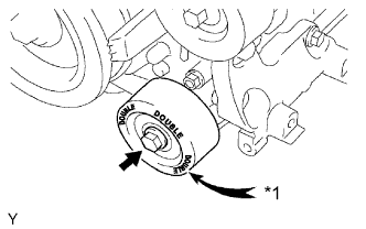 |
Install the No. 1 idler pulley with the bolt.
- Torque:
- 54 N*m{551 kgf*cm, 40 ft.*lbf}
Text in Illustration *1 "DOUBLE" - HINT:
- "DOUBLE" is marked on the No. 1 idler pulley to distinguish it from the No. 2 idler pulley.
| 2. INSTALL NO. 2 IDLER PULLEY SUB-ASSEMBLY |
w/ Idler Pulley Cover Plate:
Install the 2 idler pulley cover plates, 2 No. 2 idler pulleys and 2 No. 2 idler pulley cover plates with the 2 bolts.
- Torque:
- 54 N*m{551 kgf*cm, 40 ft.*lbf}
w/o Idler Pulley Cover Plate:
Install the 2 No. 2 idler pulleys and 2 No. 2 idler pulley cover plates with the 2 bolts.
- Torque:
- 54 N*m{551 kgf*cm, 40 ft.*lbf}
for Integrated Type:
Install the 2 No. 2 idler pulleys with the 2 bolts.
- Torque:
- 54 N*m{551 kgf*cm, 40 ft.*lbf}
| 3. INSTALL ENGINE OIL LEVEL DIPSTICK GUIDE |
Install a new O-ring to the engine oil level dipstick guide.
Text in Illustration *1 New O-Ring *a Push
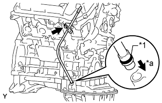 |
Apply a light coat of engine oil to the O-ring.
Push in the engine oil level dipstick guide end into the guide hole of the oil pan.
Install the engine oil level dipstick guide with the bolt.
- Torque:
- 9.0 N*m{92 kgf*cm, 80 in.*lbf}
Install the engine oil level dipstick.
| 4. INSTALL IGNITION COIL ASSEMBLY |
Install the 6 ignition coils with the 6 bolts.
- Torque:
- 10 N*m{102 kgf*cm, 7 ft.*lbf}
Connect the 6 ignition coil connectors.
| 5. INSTALL OIL FILLER CAP HOUSING |
Install a new gasket and the oil filler cap housing with the 2 nuts.
- Torque:
- 9.0 N*m{92 kgf*cm, 80 in.*lbf}
| 6. INSTALL OIL FILLER CAP SUB-ASSEMBLY |
| 7. INSTALL INTAKE MANIFOLD |
Set 2 new gaskets on each cylinder head.
- NOTICE:
- Align the port holes of the gasket and cylinder head.
- Make sure the gaskets are installed facing the proper direction.
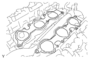 |
Set the intake manifold on the cylinder heads.
Install and uniformly tighten the 10 bolts in several passes.
- Torque:
- 26 N*m{265 kgf*cm, 19 ft.*lbf}
- HINT:
- Tighten the inner installation bolts of the intake manifold before tightening the outer bolts.
| 8. INSTALL V-RIBBED BELT TENSIONER ASSEMBLY |
 |
Temporarily install the V-ribbed belt tensioner with the 5 bolts.
Install the V-ribbed belt tensioner by tightening bolt 1 and then bolt 2.
- Torque:
- 36 N*m{367 kgf*cm, 27 ft.*lbf}
Tighten the other bolts.
- Torque:
- 36 N*m{367 kgf*cm, 27 ft.*lbf}
- Bolt Length:
Bolt Length
mm (in.)A 70 mm (2.76 in.) B 33 mm (1.30 in.)
Text in Illustration 
Bolt A 
Bolt B
| 9. INSTALL FRONT NO. 1 ENGINE MOUNTING BRACKET LH |
Install the front No. 1 engine mounting bracket LH with the 3 bolts.
- Torque:
- 43 N*m{438 kgf*cm, 32 ft.*lbf}
| 10. INSTALL FRONT NO. 1 ENGINE MOUNTING BRACKET RH |
Install the front No. 1 engine mounting bracket RH with the 4 bolts.
- Torque:
- 43 N*m{438 kgf*cm, 32 ft.*lbf}
| 11. INSTALL GENERATOR ASSEMBLY |
Install the generator with the 2 bolts.
- Torque:
- 43 N*m{438 kgf*cm, 32 ft.*lbf}
Connect the generator wire with the nut and 2 bolts.
- Torque:
- for nut:
- 9.8 N*m{100 kgf*cm, 87 in.*lbf}
- for bolt:
- 13 N*m{133 kgf*cm, 10 ft.*lbf}
Install the terminal cap.
Connect the generator connector.
| 12. INSTALL NO. 2 PCV HOSE |
| 13. INSTALL PCV HOSE |
| 14. INSTALL HEATER WATER HOSE |
| 15. INSTALL ENGINE WIRE |