Sfi System Ecm Power Source Circuit
DESCRIPTION
WIRING DIAGRAM
INSPECTION PROCEDURE
INSPECT ECM (+B, +B2 VOLTAGE)
CHECK HARNESS AND CONNECTOR (ECM - BODY GROUND)
INSPECT ECM (IGSW VOLTAGE)
INSPECT ECM (MREL VOLTAGE)
INSPECT NO.1 INTEGRATION RELAY (MAIN RELAY)
CHECK HARNESS AND CONNECTOR (NO.1 INTEGRATION RELAY - ECM, BODY GROUND)
INSPECT IGNITION SWITCH ASSEMBLY
SFI SYSTEM - ECM Power Source Circuit |
DESCRIPTION
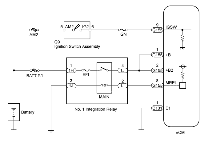
When the ignition switch is turned to ON, battery voltage is applied to the IGSW of the ECM. The output signal from the MREL terminal of the ECM causes a current to flow to the coil, closing the contacts of the MAIN relay and supplying power to either terminal +B or +B2 of the ECM.
WIRING DIAGRAM
INSPECTION PROCEDURE
- NOTICE:
- Inspect the fuses for circuits related to this system before performing the following inspection procedure.
| 1.INSPECT ECM (+B, +B2 VOLTAGE) |
Measure the voltage according to the value(s) in the table below.
- Standard Voltage:
Tester Connection
| Switch Condition
| Specified Condition
|
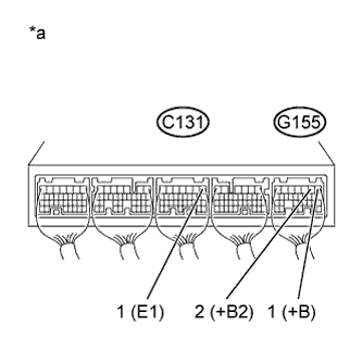
G155-1 (+B) - C131-1 (E1)
| Ignition switch ON
| 11 to 14 V
|
G155-2 (+B2) - C131-1 (E1)
| Ignition switch ON
| 11 to 14 V
|
Text in Illustration*a
| Component with harness connected
(ECM)
|
| 2.CHECK HARNESS AND CONNECTOR (ECM - BODY GROUND) |
Disconnect the ECM connector.
Measure the resistance according to the value(s) in the table below.
- Standard Resistance:
Tester Connection
| Condition
| Specified Condition
|
C131-1 (E1) - Body ground
| Always
| Below 1 Ω
|
| | REPAIR OR REPLACE HARNESS OR CONNECTOR |
|
|
| 3.INSPECT ECM (IGSW VOLTAGE) |
Measure the voltage according to the value(s) in the table below.
- Standard Voltage:
Tester Connection
| Switch Condition
| Specified Condition
|
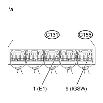
G155-9 (IGSW) - C131-1 (E1)
| Ignition switch ON
| 11 to 14 V
|
Text in Illustration*a
| Component with harness connected
(ECM)
|
| 4.INSPECT ECM (MREL VOLTAGE) |
Measure the voltage according to the value(s) in the table below.
- Standard Voltage:
Tester Connection
| Switch Condition
| Specified Condition
|
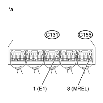
G155-8 (MREL) - C131-1 (E1)
| Ignition switch ON
| 11 to 14 V
|
Text in Illustration*a
| Component with harness connected
(ECM)
|
| 5.INSPECT NO.1 INTEGRATION RELAY (MAIN RELAY) |
Inspect the MAIN relay (HILUX_TGN26 RM000003BLB02FX_01_0019.html).
| | REPLACE NO.1 INTEGRATION RELAY |
|
|
| 6.CHECK HARNESS AND CONNECTOR (NO.1 INTEGRATION RELAY - ECM, BODY GROUND) |
Remove the No. 1 integration relay from the engine room relay block and junction block assembly.
Disconnect the ECM connector.
Measure the resistance according to the value(s) in the table below.
- Standard Resistance:
Tester Connection
| Condition
| Specified Condition
|
1J-2 - G155-8 (MREL)
| Always
| Below 1 Ω
|
1J-3 - Body ground
| Always
| Below 1 Ω
|
1J-2 or G155-8 (MREL) - Body ground
| Always
| 10 kΩ or higher
|
| | REPAIR OR REPLACE HARNESS OR CONNECTOR |
|
|
| OK |
|
|
|
| REPAIR OR REPLACE HARNESS OR CONNECTOR (TERMINAL +B OF ECM - BATTERY POSITIVE TERMINAL) |
|
| 7.INSPECT IGNITION SWITCH ASSEMBLY |
Inspect the ignition switch assembly (HILUX_TGN26 RM00000135X01OX.html).
| OK |
|
|
|
| REPAIR OR REPLACE HARNESS OR CONNECTOR (IGNITION SWITCH ASSEMBLY - ECM, BATTERY) |
|