Engine Immobiliser System Security Indicator Light Does Not Blink
DESCRIPTION
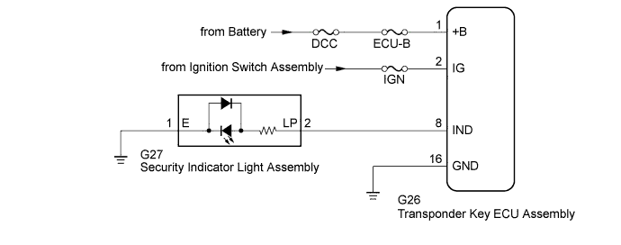
WIRING DIAGRAM
INSPECTION PROCEDURE
CHECK FOR DTC
PERFORM ACTIVE TEST USING INTELLIGENT TESTER (SECURITY INDICATOR LIGHT)
READ VALUE USING INTELLIGENT TESTER (ENGINE IMMOBILISER SYSTEM STATUS)
CHECK HARNESS AND CONNECTOR (SECURITY INDICATOR LIGHT - TRANSPONDER KEY ECU AND BODY GROUND)
REPLACE SECURITY INDICATOR LIGHT ASSEMBLY
CHECK SECURITY INDICATOR LIGHT ASSEMBLY
CHECK HARNESS AND CONNECTOR (TRANSPONDER KEY ECU - BATTERY AND BODY GROUND)
ENGINE IMMOBILISER SYSTEM - Security Indicator Light Does not Blink |
DESCRIPTION
- When the engine immobiliser system is set, the security indicator light assembly blinks continuously, but does not illuminate if the engine immobiliser system is not set.
WIRING DIAGRAM
INSPECTION PROCEDURE
- NOTICE:
- When replacing the transponder key ECU assembly, refer to Registration.
- Inspect the fuses for circuits related to this system before performing the following inspection procedure.
Check for DTCs (HILUX_TGN26 RM000000Z3I00TX.html).
- OK:
- DTC is not output.
| 2.PERFORM ACTIVE TEST USING INTELLIGENT TESTER (SECURITY INDICATOR LIGHT) |
Check that the security indicator light assembly illuminates when operating it with the Active Test (HILUX_TGN26 RM000000Z3K00SX.html).
ImmobiliserTester Display
| Test Part
| Control Range
| Diagnostic Note
|
Security Indicator
| Security indicator light
| ON or OFF
| The test is possible when the following condition is met:
- The key is in the ignition key cylinder.
|
- OK:
- Security indicator light assembly can be turned on and off using the intelligent tester.
| 3.READ VALUE USING INTELLIGENT TESTER (ENGINE IMMOBILISER SYSTEM STATUS) |
Turn the ignition switch off.
- HINT:
- When using the intelligent tester with the ignition switch off to troubleshoot: Connect the intelligent tester to the DLC3 and turn a courtesy light switch on and off at intervals of 1.5 seconds until communication between the intelligent tester and vehicle begins.
Using the intelligent tester, read the Data List (HILUX_TGN26 RM000000Z3K00SX.html).
ImmobiliserTester Display
| Measurement Item/Range
| Normal Condition
| Diagnostic Note
|
Immobiliser
| Engine immobiliser system status determined by transponder key ECU assembly / Set or Unset
| Set: Engine immobiliser set (engine start prohibited [no key in ignition key cylinder])
Unset: Engine immobiliser unset (engine start permitted [key inserted in ignition key cylinder])
| When the engine immobiliser system does not change to the unset state, this item can be used to determine if the cause is the transponder key ECU assembly.
|
- OK:
- Set (the key is not inserted in the ignition key cylinder) and Unset (the key is inserted in the ignition key cylinder) appear on the screen according to the key insertion condition.
| OK |
|
|
|
| REPLACE TRANSPONDER KEY ECU ASSEMBLY |
|
| 4.CHECK HARNESS AND CONNECTOR (SECURITY INDICATOR LIGHT - TRANSPONDER KEY ECU AND BODY GROUND) |
Disconnect the G27 security indicator light assembly connector.
Disconnect the G26 transponder key ECU assembly connector.
Measure the resistance according to the value(s) in the table below.
- Standard Resistance:
Tester Connection
| Condition
| Specified Condition
|
G27-2 (LP) - G26-8 (IND)
| Always
| Below 1 Ω
|
G27-1 (E) - Body ground
| Always
| Below 1 Ω
|
G27-2 (LP) or G26-8 (IND) - Body ground
| Always
| 10 kΩ or higher
|
| | REPAIR OR REPLACE HARNESS OR CONNECTOR |
|
|
| 5.REPLACE SECURITY INDICATOR LIGHT ASSEMBLY |
Temporarily replace the security indicator light assembly with a new or normally functioning one (HILUX_TGN26 RM00000478I00QX.html).
| 6.CHECK SECURITY INDICATOR LIGHT ASSEMBLY |
When the immobiliser is set (the ignition switch is off), check that the security indicator light assembly blinks.
- OK:
- Security indicator light assembly blinks.
| | REPLACE TRANSPONDER KEY ECU ASSEMBLY |
|
|
| OK |
|
|
|
| END (SECURITY INDICATOR LIGHT IS DEFECTIVE) |
|
| 7.CHECK HARNESS AND CONNECTOR (TRANSPONDER KEY ECU - BATTERY AND BODY GROUND) |
Disconnect the G26 transponder key ECU assembly connector.
Measure the resistance according to the value(s) in the table below.
- Standard Resistance:
Tester Connection
| Condition
| Specified Condition
|
G26-16 (GND) - Body ground
| Always
| Below 1 Ω
|
Measure the voltage according to the value(s) in the table below.
- Standard Voltage:
Tester Connection
| Condition
| Specified Condition
|
G26-1 (+B) - Body ground
| Always
| 11 to 14 V
|
G26-2 (IG) - Body ground
| Ignition switch off
| Below 1 V
|
Ignition switch ON
| 11 to 14 V
|
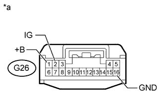
Text in Illustration*a
| Front view of wire harness connector
(to Transponder Key ECU Assembly)
|
| | REPAIR OR REPLACE HARNESS OR CONNECTOR |
|
|
| OK |
|
|
|
| REPLACE TRANSPONDER KEY ECU ASSEMBLY |
|