Dtc P0617 Starter Relay Circuit High
DESCRIPTION
MONITOR STRATEGY
TYPICAL ENABLING CONDITIONS
TYPICAL MALFUNCTION THRESHOLDS
CONFIRMATION DRIVING PATTERN
WIRING DIAGRAM
INSPECTION PROCEDURE
READ VALUE USING INTELLIGENT TESTER (STARTER SIGNAL)
REPAIR OR REPLACE HARNESS AND CONNECTOR (IGNITION SWITCH - ECM)
CHECK WHETHER DTC OUTPUT RECURS
DTC P0617 Starter Relay Circuit High |
DESCRIPTION
While the engine is being cranked, the positive battery voltage is applied to terminal STA of the ECM. If the ECM detects the starter control (STA) signal while the vehicle is being driven, it determines that there is a malfunction in the STA circuit. The ECM then illuminates the MIL and stores the DTC.This monitor runs when the vehicle is driven at 20 km/h (12.4 mph) for over 20 seconds.DTC No.
| DTC Detection Condition
| Trouble Area
|
P0617
| Conditions (a), (b) and (c) are met, and a positive (+B) battery voltage of 10.5 V or higher is applied to the ECM for 20 seconds (1 trip detection logic).
- (a) Vehicle speed is 20 km/h (12.4 mph) or more.
- (b) Engine speed is 1000 rpm or more.
- (c) STA signal is on.
| - Starter (ST) relay circuit
- Ignition switch assembly
- ECM
|
MONITOR STRATEGY
Required Sensors/Components (Main)
| Starter (ST) relay, Ignition switch assembly
|
Required Sensors/Components (Related)
| Vehicle speed sensor, Crankshaft position sensor
|
Frequency of Operation
| Continuous
|
TYPICAL ENABLING CONDITIONS
Vehicle speed
| 20 km/h (12.43 mph) or more
|
Engine speed
| 1000 rpm or more
|
TYPICAL MALFUNCTION THRESHOLDS
CONFIRMATION DRIVING PATTERN
- Connect the intelligent tester to the DLC3.
- Turn the ignition switch to ON and turn the intelligent tester on.
- Clear the DTCs (even if no DTCs are stored, perform the clear DTC operation).
- Turn the ignition switch off and wait for at least 30 seconds.
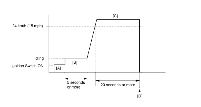
- Turn the ignition switch to ON and turn the intelligent tester on [A].
- Idle the engine for 5 seconds or more [B].
- Drive the vehicle at 24 km/h (15 mph) or more for 20 seconds or more [C].
- CAUTION:
- When performing the confirmation driving pattern, obey all speed limits and traffic laws.
- Enter the following menus: Powertrain / Engine and ECT / DTC [D].
- Read the pending DTCs.
- HINT:
- If a pending DTC is output, the system is malfunctioning.
- If a pending DTC is not output, perform the following procedure.
- Enter the following menus: Powertrain / Engine and ECT / Utility / All Readiness.
- Input the DTC: P0617.
- Check the DTC judgment result.
Intelligent Tester Display
| Description
|
NORMAL
| - DTC judgment completed
- System normal
|
ABNORMAL
| - DTC judgment completed
- System abnormal
|
INCOMPLETE
| - DTC judgment not completed
- Perform driving pattern after confirming DTC enabling conditions
|
N/A
| - Unable to perform DTC judgment
- Number of DTCs which do not fulfill DTC preconditions has reached ECU memory limit
|
- HINT:
- If the judgment result shows NORMAL, the system is normal.
- If the judgment result shows ABNORMAL, the system has a malfunction.
- If the judgment result shows INCOMPLETE or N/A, perform steps [C] and [D] again and, if necessary, extend the driving time.
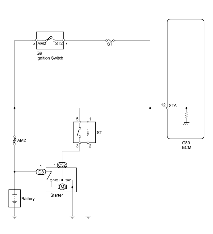
WIRING DIAGRAM
INSPECTION PROCEDURE
- HINT:
- The following troubleshooting flowchart is based on the premise that the engine can be cranked normally.
If the engine does not crank, proceed to Problem Symptoms Table (HILUX_TGN26 RM000000PDG0OAX.html).
- Read freeze frame data using the intelligent tester. Freeze frame data records the engine condition when malfunctions are detected. When troubleshooting, freeze frame data can help determine if the vehicle was moving or stationary, if the engine was warmed up or not, if the air-fuel ratio was lean or rich, and other data from the time the malfunction occurred.
| 1.READ VALUE USING INTELLIGENT TESTER (STARTER SIGNAL) |
Connect the intelligent tester to the DLC3.
Turn the ignition switch to ON and turn the intelligent tester on.
Enter the following menus: Powertrain / Engine and ECT / Data List / Starter Signal.
Check the value displayed on the intelligent tester when the ignition switch is turned to ON and when the engine is started.
- OK:
Condition
| Starter Signal
|
Ignition switch turned to ON
| Close
|
Engine started
| Open
|
| 2.REPAIR OR REPLACE HARNESS AND CONNECTOR (IGNITION SWITCH - ECM) |
| 3.CHECK WHETHER DTC OUTPUT RECURS |
Connect the intelligent tester to the DLC3.
Turn the ignition switch to ON.
Turn the intelligent tester on.
Clear the DTCs (HILUX_TGN26 RM000000PDK0XTX.html).
Drive the vehicle at more than 24 km/h (15 mph) for more than 20 seconds.
Enter the following menus: Powertrain / Engine and ECT / Trouble Code.
Read the DTCs.
ResultResult
| Proceed to
|
P0617 is output
| A
|
No DTC is output
| B
|