Terminal No. (Symbol)
| Wiring Color
| Terminal Description
| Condition
| Specified Condition
|
G145-17 (BATT) - C98-5 (E1)
| L - BR
| Battery (for measuring battery voltage and for ECM memory)
| Always
| 11 to 14 V
|
G145-22 (+BM) - C98-5 (E1)
| R-W - BR
| Power source of throttle actuator
| Always
| 11 to 14 V
|
G146-22 (IGSW) - C98-5 (E1)
| B-O - BR
| Ignition switch
| Ignition switch ON
| 11 to 14 V
|
G145-23 (+B) - C98-5 (E1)
| B - BR
| Power source of ECM
| Ignition switch ON
| 11 to 14 V
|
G146-12 (MREL) - C98-5 (E1)
| W-G - BR
| MAIN relay
| Ignition switch ON
| 11 to 14 V
|
C95-10 (VCTA) - C96-16 (E2)
| Y - BR
| Power source of sensor (specific voltage)
| Ignition switch ON
| 4.5 to 5.0 V
|
C95-3 (VTA1) - C95-9 (ETA)
| B-R - BR
| Throttle position sensor (for engine control)
| Ignition switch ON, accelerator pedal fully released
| 0.5 to 1.1 V
|
C95-3 (VTA1) - C95-9 (ETA)
| B-R - BR
| Throttle position sensor (for engine control)
| Ignition switch ON, accelerator pedal fully depressed
| 3.2 to 4.8 V
|
C95-4 (VTA2) - C95-9 (ETA)
| LG - BR
| Throttle position sensor (for sensor malfunction detection)
| Ignition switch ON, accelerator pedal fully released
| 2.1 to 3.1 V
|
C95-4 (VTA2) - C95-9 (ETA)
| LG - BR
| Throttle position sensor (for sensor malfunction detection)
| Ignition switch ON, accelerator pedal fully depressed
| 4.6 to 5.0 V
|
G146-6 (VPA) - G146-2 (EPA)
| W-L - BR-W
| Accelerator pedal position sensor (for engine control)
| Ignition switch ON, accelerator pedal fully released
| 0.5 to 1.1 V
|
G146-6 (VPA) - G146-2 (EPA)
| W-L - BR-W
| Accelerator pedal position sensor (for engine control)
| Ignition switch ON, accelerator pedal fully depressed
| 2.6 to 4.5 V
|
G146-5 (VPA2) - G146-1 (EPA2)
| GR-G - BR-Y
| Accelerator pedal position sensor (for sensor malfunction detection)
| Ignition switch ON, accelerator pedal fully released
| 1.2 to 2.0 V
|
G146-5 (VPA2) - G146-1 (EPA2)
| GR-G - BR-Y
| Accelerator pedal position sensor (for sensor malfunction detection)
| Ignition switch ON, accelerator pedal fully depressed
| 3.4 to 5.0 V
|
G146-4 (VCPA) - C98-5 (E1)
| LG-R - BR
| Power source of accelerator pedal position sensor (for VPA)
| Ignition switch ON
| 4.5 to 5.0 V
|
G146-3 (VCP2) - C98-5 (E1)
| BR-R - BR
| Power source of accelerator pedal position sensor (for VPA2)
| Ignition switch ON
| 4.5 to 5.0 V
|
C95-13 (VG) - C95-7 (E2G)
| L-W - L-R
| Mass air flow meter
| Idling, shift lever in P or N (for A/T) or neutral (for M/T), A/C switch off
| 0.5 to 3.0 V
|
C95-12 (THA) - C95-11 (ETHA)
| L-B - BR
| Intake air temperature sensor
| Idling, intake air temperature 20°C (68°F)
| 0.5 to 3.4 V
|
C95-18 (THW) - C95-17 (ETHW)
| B - BR
| Engine coolant temperature sensor
| Idling, engine coolant temperature 80°C (176°F)
| 0.2 to 1.0 V
|
C98-6 (#10) - C98-11 (E01)
| L - W-B
| Fuel injector assembly
| Ignition switch ON
| 11 to 14 V
|
C98-7 (#20) - C98-11 (E01)
| G - W-B
| Fuel injector assembly
| Ignition switch ON
| 11 to 14 V
|
C98-8 (#30) - C98-11 (E01)
| R - W-B
| Fuel injector assembly
| Ignition switch ON
| 11 to 14 V
|
C98-9 (#40) - C98-11 (E01)
| W - W-B
| Fuel injector assembly
| Ignition switch ON
| 11 to 14 V
|
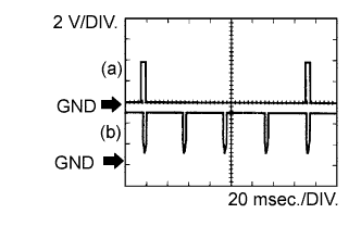
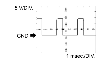
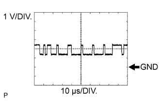
C98-6 (#10) - C98-11 (E01)
| L - W-B
| Fuel injector assembly
| Idling
| Pulse generation
(See waveform 1)
|
C98-7 (#20) - C98-11 (E01)
| G - W-B
| Fuel injector assembly
| Idling
| Pulse generation
(See waveform 1)
|
C98-8 (#30) - C98-11 (E01)
| R - W-B
| Fuel injector assembly
| Idling
| Pulse generation
(See waveform 1)
|
C98-9 (#40) - C98-11 (E01)
| W - W-B
| Fuel injector assembly
| Idling
| Pulse generation
(See waveform 1)
|
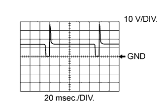
C98-1 (IGT1) - C98-5 (E1)
| R - BR
| Ignition coil assembly
(ignition signal)
| Idling
| Pulse generation
(See waveform 2)
|
C98-2 (IGT2) - C98-5 (E1)
| R-L - BR
| Ignition coil assembly
(ignition signal)
| Idling
| Pulse generation
(See waveform 2)
|
C98-3 (IGT3) - C98-5 (E1)
| G-B - BR
| Ignition coil assembly
(ignition signal)
| Idling
| Pulse generation
(See waveform 2)
|
C98-4 (IGT4) - C98-5 (E1)
| G - BR
| Ignition coil assembly
(ignition signal)
| Idling
| Pulse generation
(See waveform 2)
|
C98-10 (IGF1) - C98-5 (E1)
| G-R - BR
| Ignition coil assembly
(ignition confirmation signal)
| Ignition switch ON
| 4.5 to 5.0 V
|
C98-10 (IGF1) - C98-5 (E1)
| G-R - BR
| Ignition coil assembly
(ignition confirmation signal)
| Idling
| Pulse generation
(See waveform 2)
|
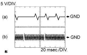
C96-11 (G2) - C96-5 (NE-)
| R - G
| Camshaft position sensor
| Idling
| Pulse generation
(See waveform 3)
|
C96-12 (NE+) - C96-5 (NE-)
| L - G
| Crankshaft position sensor
| Idling
| Pulse generation
(See waveform 3)
|
G146-25 (FC) - C98-5 (E1)
| LG-B - BR
| Fuel pump control
| Ignition switch ON
| 11 to 14 V
|
G146-25 (FC) - C98-5 (E1)
| LG-B - BR
| Fuel pump control
| Idling
| Below 1.5 V
|
G146-11 (FFR) - C98-5 (E1)
| L - BR
| Sub tank fuel pump control
| Ignition switch ON
| 11 to 14 V
|
G145-18 (DSSV) - C98-5 (E1)
| G - BR
| Sub tank solenoid valve assembly
(for fuel injection volume control)
| FFV relay ON
| 11 to 14 V
|
G145-1 (SSV) - C98-5 (E1)
| Y - BR
| Sub tank fuel cut solenoid valve assembly
(for fuel cut control)
| FFV relay ON
| 11 to 14 V
|
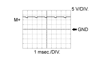
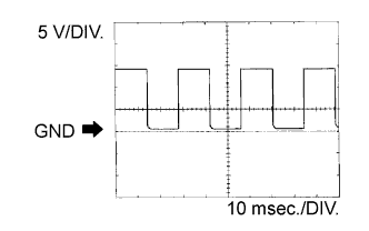
C98-14 (M+) - C98-13 (ME01)
| B - W-B
| Throttle actuator
| Idling with warm engine
| Pulse generation
(See waveform 4)
|
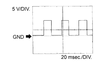
C98-15 (M-) - C98-13 (ME01)
| W - W-B
| Throttle actuator
| Idling with warm engine
| Pulse generation
(See waveform 5)
|
C97-7 (A1A+) - C98-5 (E1)
| B - BR
| Air fuel ratio sensor
| Ignition switch ON
| 3.3 V*1
|
C97-1 (A1A-) - C98-5 (E1)
| W - BR
| Air fuel ratio sensor
| Ignition switch ON
| 3.0 V*1
|
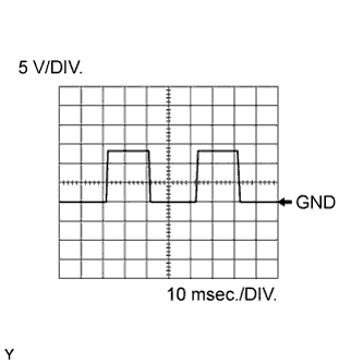
C97-13 (OX1B) - C96-16 (E2)
| B - BR
| Heated oxygen sensor
| Engine speed maintained at 2500 rpm for 2 minutes after warming up sensor
| Pulse generation
(See waveform 6)
|
C97-6 (HA1A) - C97-23 (E04)
| Y - W-B
| Air fuel ratio sensor
| Idling
| Pulse generation
(See waveform 7)
|
C97-6 (HA1A) - C97-23 (E04)
| Y - W-B
| Air fuel ratio sensor
| Ignition switch ON
| 11 to 14 V
|
C97-18 (HT1B) - C97-14 (EX1B)
| L-Y - B-R
| Heated oxygen sensor heater
| Idling
| Below 3.0 V
|
C97-18 (HT1B) - C97-14 (EX1B)
| L-Y - B-R
| Heated oxygen sensor heater
| Ignition switch ON
| 11 to 14 V
|
C95-6 (KNK1) - C95-5 (EKNK)
| B - W
| Knock sensor
| Maintain Engine speed maintained at 4000 rpm after warming up engine
| Pulse generation
(See waveform 8)
|
C96-14 (OC1+) - C96-9 (OC1-)
| P-L - Y
| Camshaft timing oil control valve assembly
| Idling
| Pulse generation
(See waveform 9)
|
C97-19 (PRG) - C98-5 (E1)
| L - BR
| Purge VSV
| Ignition switch ON
| 11 to 14 V
|
C97-19 (PRG) - C98-5 (E1)
| L - BR
| Purge VSV
| Idling
| Pulse generation
(See waveform 10)
|
G146-8 (STA) - C98-5 (E1)
| L-Y - BR
B-Y - BR*2
| Starter signal
| Shift lever in N (for A/T) or neutral (M/T), ignition switch START
| 5.5 V or higher
|
G146-18 (STP) - C98-5 (E1)
| G-W - BR
| Stop light switch
| Brake pedal depressed
| 7.5 to 14 V
|
G146-18 (STP) - C98-5 (E1)
| G-W - BR
| Stop light switch
| Brake pedal released
| Below 1.5 V
|
G145-8 (ST1-) - C98-5 (E1)
| R-L - BR
| Stop light switch
| Ignition switch ON, brake pedal depressed
| Below 1.5 V
|
G145-8 (ST1-) - C98-5 (E1)
| R-L - BR
| Stop light switch
| Ignition switch ON, brake pedal released
| 7.5 to 14 V
|
G145-13 (W) - C98-5 (E1)
| R-B - BR
| MIL
| Idling
| 11 to 14 V
|
G145-13 (W) - C98-5 (E1)
| R-B - BR
| MIL
| Ignition switch ON
| Below 3.5 V
|
C95-19 (ALT) - C98-5 (E1)
| G - BR
| Generator
| Ignition switch ON
| 11 to 14 V
|
G145-5 (ELS) - C98-5 (E1)
| G - BR
| Electric load
| Taillight switch on
| 7.5 to 14 V
|
G145-5 (ELS) - C98-5 (E1)
| G - BR
| Electric load
| Taillight switch off
| Below 1.5 V
|
G145-10 (ELS3) - C98-5 (E1)
| B - BR
| Electric load
| Rear window defogger switch on
| 7.5 to 14 V
|
G145-10 (ELS3) - C98-5 (E1)
| B - BR
| Electric load
| Rear window defogger switch off
| Below 1.5 V
|
G146-29 (TACH) - C98-5 (E1)
| B-W - BR
| Engine speed
| Idling
| Pulse generation
(See waveform 11)
|
G146-16 (SPD) - C98-5 (E1)
| V-R - BR
| Speed signal from combination meter
| Driving at 20 km/h (12 mph)
| Pulse generation
(See waveform 12)
|
G146-13 (TC) - C98-5 (E1)
| P-B - BR
| Terminal TC of DLC3
| Ignition switch ON
| 11 to 14 V
|
G145-3 (PSW) - C98-5 (E1)
| G-Y - BR
| Power steering oil pressure switch
| Steering wheel turning
| Below 1.5 V
|
G146-24 (NSW) - C98-5 (E1)*2
| L-Y - BR
| Park/Neutral switch signal
| Ignition switch ON and shift lever in P or N
| Below 1 V
|
G146-24 (NSW) - C98-5 (E1)*2
| L-Y - BR
| Park/Neutral switch signal
| Ignition switch ON and shift lever not in P or N
| 11 to 14 V
|
G146-34 (CANH) - C98-5 (E1)
| B - BR
| Signal for communication with other components
| Ignition switch ON
| Pulse generation
(See waveform 13)
|
G146-33 (CANL) - C98-5 (E1)
| W - BR
| Signal for communication with other components
| Ignition switch ON
| Pulse generation
(See waveform 14)
|
G145-6 (AIRV) - C98-5 (E1)
| V - BR
| Air switching valve for secondary air injection system
| Ignition switch ON
| 11 to 14 V
|
G145-19 (AIRP) - C98-5 (E1)
| W-L - BR
| Air pump control
| Ignition switch ON
| 11 to 14 V
|
G146-30 (AIDI) - C98-5 (E1)
| G-W - BR
| Diagnostic information signal for air injection system
| Air injection system operating
| Pulse generation
(See waveform 15)
|
C98-11 (E01) - Body ground
| W-B
| Ground
| Always
| Below 1 Ω
|
C98-12 (E02) - Body ground
| W-B
| Ground
| Always
| Below 1 Ω
|
C97-12 (E03) - Body ground
| W-B
| Ground
| Always
| Below 1 Ω
|
C97-23 (E04) - Body ground
| W-B
| Ground
| Always
| Below 1 Ω
|
C98-5 (E1) - Body ground
| BR
| Ground
| Always
| Below 1 Ω
|
C96-16 (E2) - Body ground
| BR
| Ground
| Always
| Below 1 Ω
|
G145-11 (EC) - Body ground
| R
| Ground
| Always
| Below 1 Ω
|
C98-13 (ME01) - Body ground
| W-B
| Ground
| Always
| Below 1 Ω
|
C97-24 (GE01) - Body ground
| BR
| Ground
| Always
| Below 1 Ω
|