Dtc P100B Open In Sub Fuel Tank Vsv Control Circuit
DESCRIPTION
WIRING DIAGRAM
INSPECTION PROCEDURE
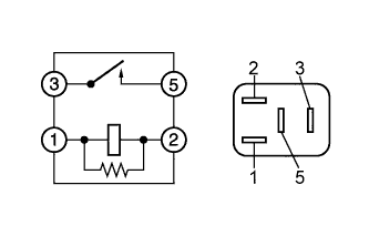
INSPECT FFV RELAY
CHECK HARNESS AND CONNECTOR (FFV RELAY - SOLENOID VALVE ASSEMBLY (FOR FUEL CUT CONTROL))
INSPECT SOLENOID VALVE ASSEMBLY (FOR FUEL CUT CONTROL)
CHECK HARNESS AND CONNECTOR (SOLENOID VALVE ASSEMBLY (FOR FUEL CUT CONTROL) - ECM)
CHECK SUB TANK FUEL PUMP CONTROL CIRCUIT
DTC P100B Open in Sub Fuel Tank VSV Control Circuit |
DTC P100C Short in Sub Fuel Tank VSV Control Circuit |
DESCRIPTION
A Flexible Fuel Vehicle (FFV) is a vehicle with an engine that can be used with a high concentration of ethyl alcohol fuel.This FFV uses a sub tank system, which allows fuel (with a gasoline concentration of 78% or more) to be injected to the fuel delivery spacer from the sub tank when the ambient temperature is low to enhance low-temperature startability.The fuel volume is controlled by the ECM and varies depending on the duty ratio of the fuel injection volume control solenoid valve.If the fuel injection volume control solenoid valve is stuck open, the fuel cut solenoid valve will operate and cut the fuel flow based on signals from the ECM, preventing the fuel from being drawn out of the sub tank due to vacuum from the engine.DTC No.
| DTC Detection Condition
| Trouble Area
|
P100B
| - All conditions are met (1 trip detection logic):
- FFR signal is on.
- SSV signal is off.
- Low voltage at terminal SSV continues for 1 second or more.
| - Open in solenoid valve assembly (for fuel cut control) circuit
- Solenoid valve assembly (for fuel cut control)
- FFV relay
- ECM
|
P100C
| - All conditions are met (1 trip detection logic):
- FFR signal is off.
- SSV signal is off.
- High voltage at terminal SSV continues for 10 seconds or more.
| - Short in solenoid valve assembly (for fuel cut control) circuit
- Solenoid valve assembly (for fuel cut control)
- FFV relay
- ECM
|
WIRING DIAGRAM
Refer to DTC P1001 (HILUX_TGN26 RM0000033SK00KX_02.html).
INSPECTION PROCEDURE
- HINT:
- Read freeze frame data using the intelligent tester. The ECM records vehicle and driving condition information as freeze frame data the moment a DTC is stored. When troubleshooting, freeze frame data can help determine if the vehicle was moving or stationary, if the engine was warmed up or not, if the air fuel ratio was lean or rich, and other data from the time the malfunction occurred.
Remove the FFV relay from the engine room relay block.
Measure the resistance according to the value(s) in the table below.
- Standard Resistance:
Tester Connection
| Condition
| Specified Condition
|
3 - 5
| Battery voltage is not applied between terminals 1 and 2
| 10 kΩ or higher
|
3 - 5
| Battery voltage is applied between terminals 1 and 2
| Below 1 Ω
|
Reinstall the FFV relay.
| 2.CHECK HARNESS AND CONNECTOR (FFV RELAY - SOLENOID VALVE ASSEMBLY (FOR FUEL CUT CONTROL)) |
Remove the FFV relay from the engine room relay block.
Disconnect the solenoid valve assembly (for fuel cut control) connector.
Measure the resistance according to the value(s) in the table below.
- Standard Resistance (Check for Open):
Tester Connection
| Condition
| Specified Condition
|
FFV relay terminal (3) - A69-2 (SFC+)
| Always
| Below 1 Ω
|
- Standard Resistance (Check for Short):
Tester Connection
| Condition
| Specified Condition
|
FFV relay terminal (3) or A69-2 (SFC+) - Body ground
| Always
| 10 kΩ or higher
|
Reinstall the FFV relay.
Reconnect the solenoid valve assembly (for fuel cut control) connector.
| | REPAIR OR REPLACE HARNESS OR CONNECTOR (FFV RELAY - SOLENOID VALVE (FOR FUEL CUT CONTROL)) |
|
|
| 3.INSPECT SOLENOID VALVE ASSEMBLY (FOR FUEL CUT CONTROL) |
Inspect the solenoid valve assembly (for fuel cut control) (HILUX_TGN26 RM0000033XQ00CX.html).
| 4.CHECK HARNESS AND CONNECTOR (SOLENOID VALVE ASSEMBLY (FOR FUEL CUT CONTROL) - ECM) |
Disconnect the solenoid valve assembly (for fuel cut control) connector.
Disconnect the ECM connector.
Measure the resistance according to the value(s) in the table below.
- Standard Resistance (Check for Open):
Tester Connection
| Condition
| Specified Condition
|
A69-1 (SFC-) - G145-1 (SSV)
| Always
| Below 1 Ω
|
- Standard Resistance (Check for Short):
Tester Connection
| Condition
| Specified Condition
|
A69-1 (SFC-) or G145-1 (SSV) - Body ground
| Always
| 10 kΩ or higher
|
Reconnect the solenoid valve assembly (for fuel cut control) connector.
Reconnect the ECM connector.
| | REPAIR OR REPLACE HARNESS OR CONNECTOR (SOLENOID VALVE ASSEMBLY (FOR FUEL CUT CONTROL) - ECM) |
|
|
| 5.CHECK SUB TANK FUEL PUMP CONTROL CIRCUIT |
Check the sub tank fuel pump control circuit (HILUX_TGN26 RM0000033U200KX.html).
| | REPAIR OR REPLACE SUB TANK FUEL PUMP CONTROL CIRCUIT |
|
|