Dtc P0201 Injector Circuit / Open - (Cylinder 1)
DESCRIPTION
WIRING DIAGRAM
INSPECTION PROCEDURE
CHECK FUEL INJECTOR ASSEMBLY (POWER SOURCE)
INSPECT FUEL INJECTOR ASSEMBLY
CHECK HARNESS AND CONNECTOR (FUEL INJECTOR ASSEMBLY - ECM)
CHECK HARNESS AND CONNECTOR (ECM - BODY GROUND)
DTC P0201 Injector Circuit / Open - (Cylinder 1) |
DTC P0202 Injector Circuit / Open - (Cylinder 2) |
DTC P0203 Injector Circuit / Open - (Cylinder 3) |
DTC P0204 Injector Circuit / Open - (Cylinder 4) |
DESCRIPTION
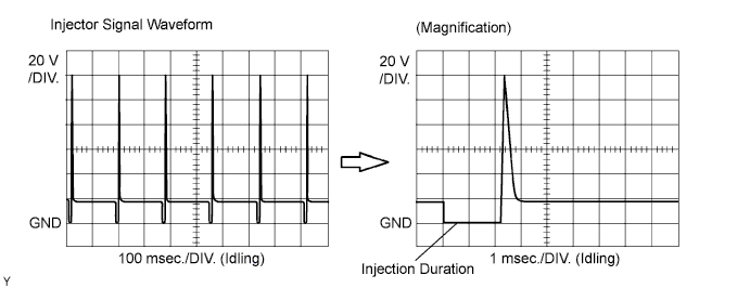
The fuel injector assemblies are located on the intake manifold assembly. They inject fuel into the cylinders based on the signals from the ECM. Reference: Inspection Using OscilloscopeWith the engine idling, check the waveform between terminals #10 to #40 and E01 of the ECM connectors.- HINT:
- The correct waveform is as shown in the diagram below.
DTC No.
| DTC Detection Condition
| Trouble Area
|
P0201
P0202
P0203
P0204
| Current is not applied to the injector more than 10 times with the engine running.
(1 trip detection logic)
| - Open or short in fuel injector circuit
- Fuel injector assembly
- ECM
|
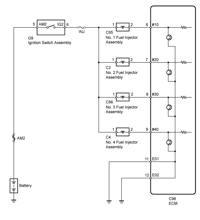
WIRING DIAGRAM
INSPECTION PROCEDURE
- HINT:
- If DTC P0201 is set, check the No. 1 injector circuit.
- If DTC P0202 is set, check the No. 2 injector circuit.
- If DTC P0203 is set, check the No. 3 injector circuit.
- If DTC P0204 is set, check the No. 4 injector circuit.
- Read freeze frame data using the intelligent tester. The ECM records vehicle and driving condition information as freeze frame data the moment a DTC is stored. When troubleshooting, freeze frame data can help determine if the vehicle was moving or stationary, if the engine was warmed up or not, if the air fuel ratio was lean or rich, and other data from the time the malfunction occurred.
| 1.CHECK FUEL INJECTOR ASSEMBLY (POWER SOURCE) |
Disconnect the fuel injector assembly connectors.
Turn the ignition switch to ON.
Measure the voltage according to the value(s) in the table below.
- Standard Voltage:
Tester Connection
| Switch Condition
| Specified Condition
|
C65-1 - Body ground
| Ignition switch ON
| 11 to 14 V
|
C2-1 - Body ground
| Ignition switch ON
| 11 to 14 V
|
C66-1 - Body ground
| Ignition switch ON
| 11 to 14 V
|
C4-1 - Body ground
| Ignition switch ON
| 11 to 14 V
|
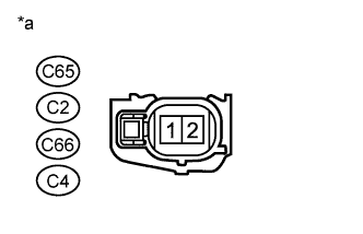
Text in Illustration*a
| Front view of wire harness connector
(to Fuel Injector Assembly)
|
Reconnect the fuel injector assembly connectors.
| | REPAIR OR REPLACE HARNESS OR CONNECTOR (INTEGRATION RELAY - FUEL INJECTOR ASSEMBLY) |
|
|
| 2.INSPECT FUEL INJECTOR ASSEMBLY |
Inspect the fuel injector assembly (HILUX_TGN26 RM000000YL901AX.html).
| 3.CHECK HARNESS AND CONNECTOR (FUEL INJECTOR ASSEMBLY - ECM) |
Disconnect the fuel injector assembly connectors.
Disconnect the ECM connector.
Measure the resistance according to the value(s) in the table below.
- Standard Resistance (Check for Open):
Tester Connection
| Condition
| Specified Condition
|
C65-2 - C98-6 (#10)
| Always
| Below 1 Ω
|
C2-2 - C98-7 (#20)
| Always
| Below 1 Ω
|
C66-2 - C98-8 (#30)
| Always
| Below 1 Ω
|
C4-2 - C98-9 (#40)
| Always
| Below 1 Ω
|
- Standard Resistance (Check for Short):
Tester Connection
| Condition
| Specified Condition
|
C65-2 or C98-6 (#10) - Body ground
| Always
| 10 kΩ or higher
|
C2-2 or C98-7 (#20) - Body ground
| Always
| 10 kΩ or higher
|
C66-2 or C98-8 (#30) - Body ground
| Always
| 10 kΩ or higher
|
C4-2 or C98-9 (#40) - Body ground
| Always
| 10 kΩ or higher
|
Reconnect the fuel injector assembly connectors.
Reconnect the ECM connector.
| | REPAIR OR REPLACE HARNESS OR CONNECTOR (FUEL INJECTOR ASSEMBLY - ECM) |
|
|
| 4.CHECK HARNESS AND CONNECTOR (ECM - BODY GROUND) |
Disconnect the ECM connectors.
Measure the resistance according to the value(s) in the table below.
- Standard Resistance (Check for Open):
Tester Connection
| Condition
| Specified Condition
|
C98-11 (E01) - Body ground
| Always
| Below 1 Ω
|
C98-12 (E02) - Body ground
| Always
| Below 1 Ω
|
Reconnect the ECM connectors.
| | REPAIR OR REPLACE HARNESS OR CONNECTOR (ECM - BODY GROUND) |
|
|