Ecd System (For I-Art) Injector Circuit
DESCRIPTION
WIRING DIAGRAM
INSPECTION PROCEDURE
CHECK INJECTOR DRIVER (POWER SOURCE)
INSPECT NO. 1 INTEGRATION RELAY (EDU RELAY)
CHECK HARNESS AND CONNECTOR (INJECTOR DRIVER - NO. 1 INTEGRATION RELAY)
CHECK HARNESS AND CONNECTOR (ECM - NO. 1 INTEGRATION RELAY)
ECD SYSTEM (for i-ART) - Injector Circuit |
DESCRIPTION
The injector driver drives the injectors at high speeds with a high-voltage DC/DC converter. The ECM constantly monitors the injector driver and stops the engine if an abnormal condition is detected.
WIRING DIAGRAM
Refer to DTC P0201 (HILUX_TGN26 RM00000187V063X_06.html).
INSPECTION PROCEDURE
- NOTICE:
- Inspect the fuses of circuits related to this system before performing the following inspection procedure.
- After replacing the ECM, the new ECM needs registration (HILUX_TGN26 RM0000012XK05AX.html) and initialization (HILUX_TGN26 RM000000TIN058X.html).
| 1.CHECK INJECTOR DRIVER (POWER SOURCE) |
Disconnect the injector driver connectors.
Measure the voltage according to the value(s) in the table below.
- Standard Voltage:
Tester Connection
| Switch Condition
| Specified Condition
|
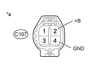
C107-2 (+B) - C107-4 (GND)
| Ignition switch ON
| 11 to 14 V
|
Text in Illustration*a
| Front view of wire harness connector
(to Injector Driver)
|
Reconnect the injector driver connectors.
| 2.INSPECT NO. 1 INTEGRATION RELAY (EDU RELAY) |
Inspect the No. 1 integration relay (EDU relay) (HILUX_TGN26 RM00000469100QX_01_0005.html).
| | REPLACE NO. 1 INTEGRATION RELAY (EDU RELAY) |
|
|
| 3.CHECK HARNESS AND CONNECTOR (INJECTOR DRIVER - NO. 1 INTEGRATION RELAY) |
Remove the No. 1 integration relay from the engine room relay block and junction block assembly.
Disconnect the injector driver connector.
Disconnect the ECM connector.
Measure the resistance according to the value(s) in the table below.
- Standard Resistance:
Tester Connection
| Condition
| Specified Condition
|
C107-2 (+B) - 1J-8
| Always
| Below 1 Ω
|
C107-4 (GND) - Body ground
| Always
| Below 1 Ω
|
1J-5 - 1J-6
| Always
| Below 1 Ω
|
C107-2 (+B) or 1J-8 - Body ground
| Always
| 10 kΩ or higher
|
1J-5 or 1J-6 - Body ground
| Always
| 10 kΩ or higher
|
Reconnect the injector driver connector.
Reinstall the No. 1 integration relay.
| | REPAIR OR REPLACE HARNESS OR CONNECTOR |
|
|
| 4.CHECK HARNESS AND CONNECTOR (ECM - NO. 1 INTEGRATION RELAY) |
Remove the No. 1 integration relay from the engine room relay block and junction block assembly.
Disconnect the ECM connector.
Measure the resistance according to the value(s) in the table below.
- Standard Resistance:
Tester Connection
| Condition
| Specified Condition
|
G156-12 (IREL) - 1J-7
| Always
| Below 1 Ω
|
G156-12 (IREL) or 1J-7 - Body ground
| Always
| 10 kΩ or higher
|
Reconnect the ECM connector.
Reinstall the No. 1 integration relay.
| | REPAIR OR REPLACE HARNESS OR CONNECTOR |
|
|