Cylinder Head Gasket -- Installation |
| 1. INSTALL NO. 2 CYLINDER HEAD GASKET |
Remove any old packing (FIPG) material and be careful not to drop any oil on the contact surfaces of the cylinder head LH or cylinder block.
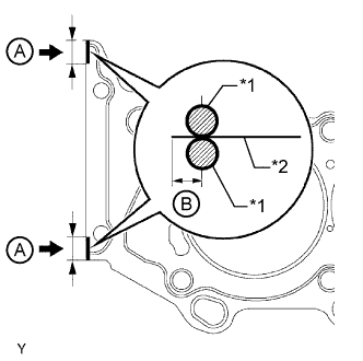
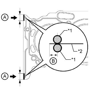
Apply seal packing to a new No. 2 cylinder head gasket as shown in the illustration.
- Seal packing:
- Toyota Genuine Seal Packing Black, Three Bond 1207B or equivalent
- Standard seal diameter:
- 2.5 to 3.0 mm (0.0984 to 0.118 in.)
Seal Packing Application Range A 10 to 15 mm (0.394 to 0.591 in.) B 1.25 to 1.5 mm (0.0492 to 0.0591 in.) Text in Illustration *1 Seal Packing *2 Gasket - NOTICE:
- Remove any oil from the contact surface.
- Install the No. 2 cylinder head gasket within 3 minutes after applying the seal packing.
- Do not add engine oil within 2 hours of installation.
 |
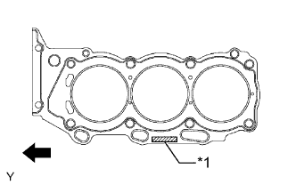
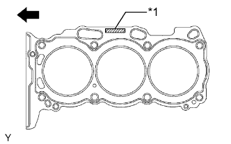
Place the No. 2 cylinder head gasket on the cylinder block surface with the front face of the Lot No. stamp upward.
Text in Illustration *1 Lot No. 
Engine Front - NOTICE:
- Make sure that the gasket is installed facing the proper direction.
 |
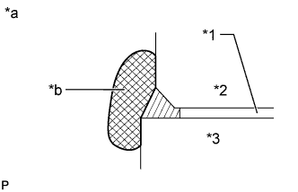
Seal packing will seep out from the front side of engine. Thoroughly wipe off the seal packing that seeps out.
Text in Illustration *1 No. 2 Cylinder Head Gasket *2 Cylinder Head LH *3 Cylinder Block *a Engine Front Side *b Wipe Clean
 |
| 2. INSTALL CYLINDER HEAD LH |
Place the cylinder head LH on the cylinder block.
- NOTICE:
- Gently place the cylinder head LH in order not to damage the gasket with the bottom part of the head.
- Make sure that no oil is on the mounting surface of the cylinder head LH.
- HINT:
- The cylinder head bolts are tightened in 2 progressive steps.
Apply a light coat of engine oil to the threads and under the heads of the cylinder head bolts.
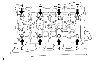
Step 1:
Using a 10 mm bi-hexagon wrench, install and uniformly tighten the 8 cylinder head bolts with the plate washers in several steps in the sequence shown in the illustration.
- Torque:
- 36 N*m{367 kgf*cm, 27 ft.*lbf}
- NOTICE:
- Do not drop the washers into the cylinder head LH.
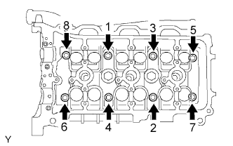 |
Step 2:
Mark the front side of each cylinder head bolt head with paint.
Tighten the cylinder head bolts another 180°.
Check that the paint marks are now at a 180° angle to the front.
Install the 2 bolts in the order shown in the illustration.
- Torque:
- 30 N*m{306 kgf*cm, 22 ft.*lbf}
- NOTICE:
- Thoroughly wipe clean any seal packing.
 |
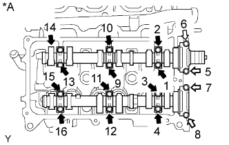
| 3. INSTALL NO. 3 CAMSHAFT SUB-ASSEMBLY AND NO. 4 CAMSHAFT SUB-ASSEMBLY |
Place the 2 camshafts onto the cylinder head with the cam lobes of the No. 2 cylinder oriented as shown in the illustration.
Text in Illustration *A for Bank 2
 |
Set the 8 bearing caps in their proper locations.
Text in Illustration *A for Bank 2
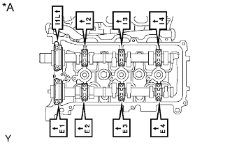 |
Apply a light coat of engine oil to the threads and under the heads of the bearing cap bolts.
Uniformly install the 16 bolts in several steps in the order shown in the illustration.
- Torque:
- for 10 mm head bolt:
- 9.0 N*m{92 kgf*cm, 80 in.*lbf}
- for 12 mm head bolt:
- 24 N*m{245 kgf*cm, 18 ft.*lbf}
Text in Illustration *A for Bank 2 10 mm Head Bolt 
12 mm Head Bolt
 |
| 4. INSTALL CYLINDER HEAD GASKET |
Remove any old packing (FIPG) material and be careful not to drop any oil on the contact surfaces of the cylinder head or cylinder block.
Apply seal packing to a new cylinder head gasket as shown in the illustration.
- Seal packing:
- Toyota Genuine Seal Packing Black, Three Bond 1207B or equivalent
- Standard seal diameter:
- 2.5 to 3.0 mm (0.0984 to 0.118 in.)
Seal Packing Application Range A 10 to 15 mm (0.394 to 0.591 in.) B 1.25 to 1.5 mm (0.0492 to 0.0591 in.) Text in Illustration *1 Seal Packing *2 Gasket - NOTICE:
- Remove any oil from the contact surface.
- Install the cylinder head gasket within 3 minutes after applying the seal packing.
- Do not add engine oil within 2 hours of installation.
 |
Place the cylinder head gasket on the cylinder block surface with the front face of the Lot No. stamp upward.
Text in Illustration *1 Lot No. Engine Front - NOTICE:
- Make sure that the gasket is installed facing the proper direction.
 |
| 5. INSTALL CYLINDER HEAD SUB-ASSEMBLY |
Place the cylinder head RH on the cylinder block.
- NOTICE:
- Gently place the cylinder head in order not to damage the gasket with the bottom part of the head.
- Make sure that no oil is on the mounting surface of the cylinder head.
- HINT:
- The cylinder head bolts are tightened in 2 progressive steps.
Apply a light coat of engine oil to the threads and under the heads of the cylinder head bolts.
Step 1:
Using a 10 mm bi-hexagon wrench, install and uniformly tighten the 8 cylinder head bolts with the plate washers in several steps in the sequence shown in the illustration.
- Torque:
- 36 N*m{367 kgf*cm, 27 ft.*lbf}
- NOTICE:
- Do not drop the washers into the cylinder head.
 |
Step 2:
Mark the front side of each cylinder head bolt head with paint.
Tighten the cylinder head bolts another 180°.
Check that the paint marks are now at a 180° angle to the front.
Seal packing will seep out from the front side of engine. Thoroughly wipe off the seal packing that seeps out.
Text in Illustration *1 Cylinder Head Gasket *2 Cylinder Head *3 Cylinder Block *a Engine Front Side *b Wipe Clean
|
| 6. INSTALL NO. 1 CAMSHAFT BEARING |
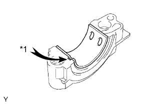
Align the bearing claw with the groove of the No. 1 camshaft bearing cap and push in the camshaft bearing.
Text in Illustration *1 Claw - NOTICE:
- Install the bearing while aligning it with the oil hole in the No. 1 camshaft bearing cap.
- Clean the backside of the bearing and the bearing surface of the No. 1 camshaft bearing cap and do not allow any oil or grease to contact the parts.
 |
| 7. INSTALL NO. 2 CAMSHAFT BEARING |
Install the No. 2 camshaft bearing to the cylinder head.
- NOTICE:
- Clean the backside of the bearing and the bearing surface of the cylinder head and do not allow any oil or grease to contact the parts.
| 8. INSTALL CAMSHAFT AND NO. 2 CAMSHAFT |
- NOTICE:
- As the thrust clearance of the camshaft is small, the camshaft must be kept level while it is being installed. If the camshaft is not kept level, the portion of the cylinder head which receives the shaft thrust may crack or be damaged, causing the camshaft to seize or break. To avoid this, the following steps should be carried out.
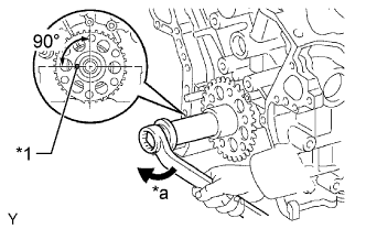
Set the crankshaft position.
Using the crankshaft pulley set bolt, turn the crankshaft and set the crankshaft set key to the left horizontal position.
Text in Illustration *1 Set Key *a Turn - NOTICE:
- Having the crankshaft at the wrong angle can cause the piston head and valve head to come into contact with each other when you install the camshaft, causing damage. So always set the crankshaft at the correct angle.
 |
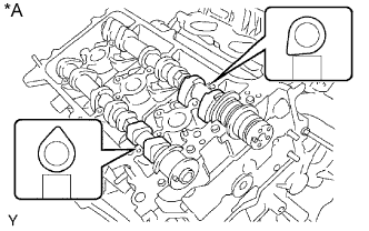
Apply new engine oil to the thrust portion and journals of the camshafts.
Place the 2 camshafts onto the cylinder head with the cam lobes of the No. 1 cylinder oriented shown in the illustration.
Text in Illustration *A for Bank 1
 |
Set the 8 bearing caps in their proper locations.
Text in Illustration *A for Bank 1
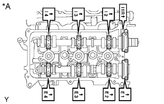 |
Apply a light coat of engine oil to the threads and under the heads of the bearing cap bolts.
 |
Uniformly install the 16 bolts in several steps in the order shown in the illustration.
- Torque:
- for 10 mm head bolt:
- 9.0 N*m{92 kgf*cm, 80 in.*lbf}
- for 12 mm head bolt:
- 24 N*m{245 kgf*cm, 18 ft.*lbf}
Text in Illustration *A for Bank 1 10 mm Head Bolt 12 mm Head Bolt
Using a wrench, turn the camshafts clockwise until the camshaft knock pin is at a position 90° to the cylinder head.
Text in Illustration *A for Bank 1 *a Turn
 |
| 9. INSTALL NO. 2 CHAIN TENSIONER ASSEMBLY |
While pushing in the tensioner, insert a pin with a diameter of 1.0 mm (0.0394 in.) into the hole to fix the tensioner in place.
Text in Illustration *a Push
 |
Install the No. 2 chain tensioner with the bolt.
- Torque:
- 21 N*m{214 kgf*cm, 15 ft.*lbf}
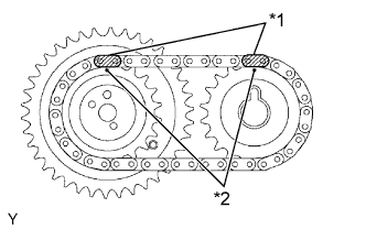
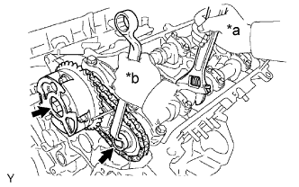
| 10. INSTALL CAMSHAFT TIMING GEARS AND NO. 2 CHAIN (for Bank 1) |
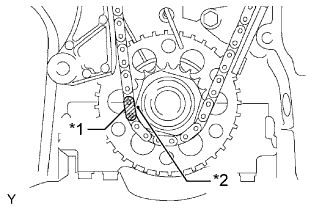
Align the mark links of the No. 2 chain with the timing marks (1-dot mark) of the camshaft timing gear and sprocket as shown in the illustration.
Text in Illustration *1 Mark Link (Yellow) *2 Timing Mark
 |
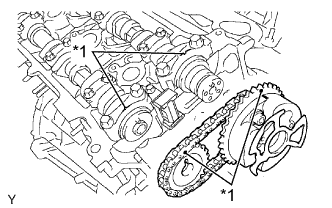
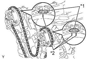
Align the timing marks on the camshaft timing gear and sprocket with the timing marks on the bearing caps and install the camshaft timing gear and sprocket together with the No. 2 chain to the camshafts.
Text in Illustration *1 Timing Mark
 |
Temporarily install the 2 camshaft timing gear bolts.
- NOTICE:
- Do not forcibly push the camshaft timing gear assembly onto the camshaft when installing it.
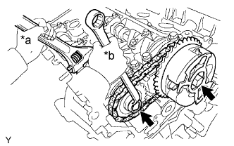
Hold the hexagonal portion of the camshaft with a wrench and tighten the 2 bolts.
- Torque:
- 100 N*m{1020 kgf*cm, 74 ft.*lbf}
Text in Illustration *a Hold *b Tighten
 |
Remove the pin from the No. 2 chain tensioner.
| 11. INSTALL NO. 3 CHAIN TENSIONER ASSEMBLY |
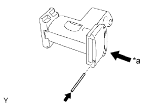
While pushing in the tensioner, insert a pin with a diameter of 1.0 mm (0.0394 in.) into the hole to fix the tensioner in place.
Text in Illustration *a Push
 |
Install the No. 3 chain tensioner with the bolt.
- Torque:
- 21 N*m{214 kgf*cm, 15 ft.*lbf}
| 12. INSTALL CAMSHAFT TIMING GEARS AND NO. 2 CHAIN (for Bank 2) |
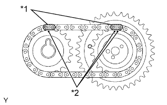
Align the mark links of the No. 2 chain with the timing marks (1-dot mark and 2-dot mark) of the camshaft timing gear and sprocket as shown in the illustration.
Text in Illustration *1 Mark Link (Yellow) *2 Timing Mark
 |
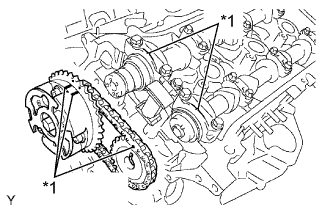
Align the timing marks on the camshaft timing gear and sprocket with the timing marks on the bearing caps and install the camshaft timing gear and sprocket together with the No. 2 chain to the camshafts.
Text in Illustration *1 Timing Mark
 |
Temporarily install the 2 camshaft timing gear bolts.
- NOTICE:
- Do not forcibly push the camshaft timing gear assembly onto the camshaft when installing it.
Hold the hexagonal portion of the camshaft with a wrench and tighten the 2 bolts.
- Torque:
- 100 N*m{1020 kgf*cm, 74 ft.*lbf}
Text in Illustration *a Hold *b Tighten
 |
Remove the pin from the No. 3 chain tensioner.
| 13. INSTALL NO. 1 CHAIN VIBRATION DAMPER |
Install the No. 1 chain vibration damper with the 2 bolts.
- Torque:
- 19 N*m{194 kgf*cm, 14 ft.*lbf}
| 14. INSTALL CHAIN TENSIONER SLIPPER |
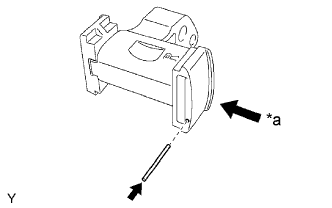
| 15. INSTALL NO. 1 CHAIN TENSIONER ASSEMBLY |
While turning the stopper plate of the tensioner clockwise, push in the plunger of the tensioner as shown in the illustration.
Text in Illustration *1 Stopper Plate *a Push
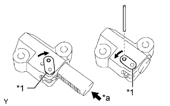 |
While turning the stopper plate of the tensioner counterclockwise, insert a bar with a diameter of 3.5 mm (0.138 in.) into the holes in the stopper plate and tensioner to fix the stopper plate in place.
Install the No. 1 chain tensioner with the 2 bolts.
- Torque:
- 10 N*m{102 kgf*cm, 7 ft.*lbf}
| 16. INSTALL CHAIN SUB-ASSEMBLY |
Set the No. 1 cylinder to TDC/compression.
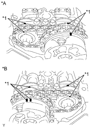
Align the timing marks of the camshaft timing gears and sprockets with the timing marks of the bearing caps.
Text in Illustration *A for Bank 1 *B for Bank 2 *1 Timing Mark Install the crankshaft pulley set bolt and turn the crankshaft to align the crankshaft set key with the timing line of the cylinder block.
Text in Illustration *1 Timing Line *2 Set Key
 |
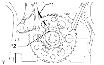
Align the mark link with the timing mark of the crankshaft timing gear.
Text in Illustration *1 Mark Link (Yellow) *2 Timing Mark
 |
Align the mark links with the timing marks of the camshaft timing gears and install the chain.
Text in Illustration *1 Mark Link (Orange) *2 Timing Mark
 |
| 17. INSTALL NO. 2 CHAIN VIBRATION DAMPER |
Install the 2 No. 2 chain vibration dampers.
| 18. INSTALL NO. 1 IDLE GEAR SHAFT |
Apply a light coat of engine oil to the sliding surface of the No. 1 idle gear shaft.
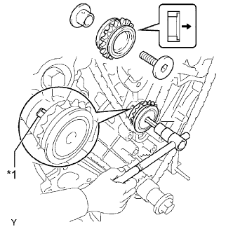
Temporarily install the No. 1 idle gear shaft and idle gear together with the No. 2 idle gear shaft while aligning the knock pin of the No. 1 idle gear shaft with the knock pin groove of the cylinder block.
Text in Illustration *1 Knock Pin Forward - NOTICE:
- Make sure that the idle gear is installed facing the proper direction.
 |
Using a 10 mm hexagon wrench, tighten the No. 2 idle gear shaft.
- Torque:
- 60 N*m{612 kgf*cm, 44 ft.*lbf}
Remove the bar from the No. 1 chain tensioner.
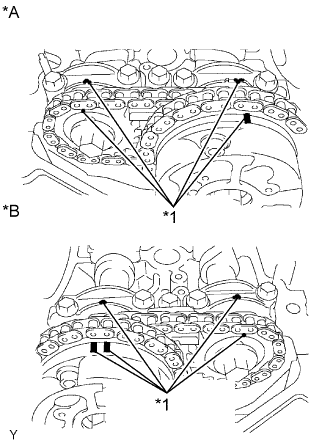
| 19. SET NO. 1 CYLINDER TO TDC/COMPRESSION |
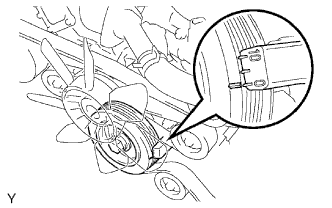
Turn the crankshaft pulley and align its groove with the "0" timing mark of the timing chain cover.
 |
Check that the timing marks of the camshaft timing gears are aligned with the timing marks of the bearing cap as shown in the illustration.
If not, turn the crankshaft 1 complete revolution (360°) and align the timing marks as above.Text in Illustration *A for Bank 1 *B for Bank 2 *1 Timing Mark
 |
| 20. INSTALL REAR WATER BY-PASS JOINT |
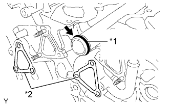
Apply soapy water to a new O-ring and install it to the No. 1 water outlet pipe. Then install 2 new gaskets to the water ports LH and RH.
Text in Illustration *1 New O-Ring *2 New Gasket
 |
Install the rear water by-pass joint with the 2 bolts and 4 nuts.
- Torque:
- for bolt:
- 10 N*m{102 kgf*cm, 7 ft.*lbf}
- for nut:
- 9.0 N*m{92 kgf*cm, 80 in.*lbf}
| 21. INSTALL TIMING CHAIN COVER SUB-ASSEMBLY |