INSTALL CAMSHAFT TIMING OIL CONTROL VALVE ASSEMBLY (for Bank 2)
INSTALL CAMSHAFT TIMING OIL CONTROL VALVE ASSEMBLY (for Bank 1)
Oil Pump -- Installation |
| 1. INSTALL TIMING CHAIN COVER SUB-ASSEMBLY |
Remove any old packing (FIPG) material and be careful not to drop any oil on the contact surfaces of the timing chain cover, cylinder head and cylinder block.
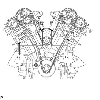
Install a new O-ring to the cylinder head for bank 2.
Apply seal packing as shown in the illustration.
- Seal packing:
- Toyota Genuine Seal Packing Black, Three Bond 1207B or equivalent
- Standard seal diameter:
- 3.5 to 4.5 mm (0.138 to 0.177 in.)
Text in Illustration *1 Seal Packing
 |
Apply seal packing in a continuous line to the timing chain cover as shown in the illustration.
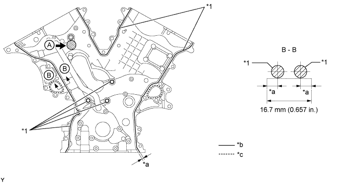
Text in Illustration *1 Seal Packing - - *a Application Position from Inside Seal Line *b Continuous line area *c Dashed line area - - - Seal Packing:
Item Seal Packing Continuous Line Area Toyota Genuine Seal Packing Black, Three Bond 1207B or equivalent Dashed Line Area Toyota Genuine Seal Packing 1282B, Three Bond 1282B or equivalent
- Application Specification:
Seal Packing Diameter Application Position from Inside Seal Line 3.5 to 4.5 mm (0.138 to 0.177 in.) 3.0 to 4.0 mm (0.118 to 0.157 in.)
- NOTICE:
- Install the timing chain cover within 3 minutes after applying seal packing. After installing it, the timing chain cover bolts and nuts must be tightened within 15 minutes. Otherwise the seal packing must be removed and reapplied.
- Do not apply seal packing to "A" shown in the illustration.
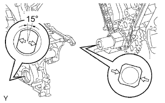
Align the keyway of the oil pump drive rotor with the rectangular portion of the crankshaft timing gear and slide the timing chain cover into place.
 |
Install the timing chain cover with the 24 bolts labeled A and B, and the 2 nuts. Tighten the bolts and nuts uniformly in several steps.
- Torque:
- 23 N*m{235 kgf*cm, 17 ft.*lbf}
- Standard Bolt:
Item Length Bolt A 25 mm (0.984 in.) Bolt B 55 mm (2.17 in.)
Text in Illustration 
Bolt A 
Bolt B 
Nut - NOTICE:
- Make sure not to wrap the chain and slipper over the timing chain cover seal line.
- Make sure that there is no oil on the bolt threads.
 |
| 2. INSTALL FRONT CRANKSHAFT OIL SEAL |
Apply MP grease to the lip of a new front crankshaft oil seal.
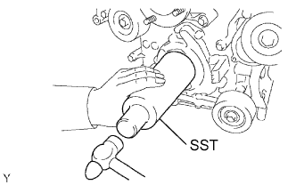 |
Using SST and a hammer, tap in the front crankshaft oil seal until its surface is flush with the timing chain cover edge.
- SST
- 09226-10010
- NOTICE:
- Keep the lip free from foreign matter.
- Do not tap the oil seal at an angle.
| 3. INSTALL OIL FILTER BRACKET SUB-ASSEMBLY |
Install a new gasket and the oil filter bracket with the 3 bolts and 2 nuts.
- Torque:
- 19 N*m{194 kgf*cm, 14 ft.*lbf}
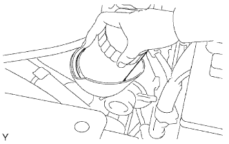
| 4. INSTALL OIL FILTER SUB-ASSEMBLY |
Check and clean the oil filter installation surface.
Apply clean engine oil to the gasket of a new oil filter.
Lightly screw the oil filter into place by hand. Tighten it until the gasket contacts the seat.
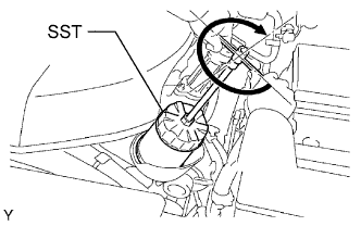
 |
Using SST, tighten the oil filter.
- SST
- 09228-07501
Text in Illustration 3/4 Turn Depending on the work space available, choose from the following.
If enough space is available, use a torque wrench to tighten the oil filter.- Torque:
- 18 N*m{184 kgf*cm, 13 ft.*lbf}
 |
| 5. INSTALL CYLINDER HEAD COVER SUB-ASSEMBLY LH |
Remove any old packing (FIPG) material and be careful not to drop any oil on the contact surfaces of the cylinder head, timing chain cover and cylinder head cover.
Apply seal packing as shown in the illustration.
- Seal packing:
- Toyota Genuine Seal Packing Black, Three Bond 1207B or equivalent
- Standard seal diameter:
- 2.0 to 3.0 mm (0.0787 to 0.118 in.)
Text in Illustration *1 Seal Packing - NOTICE:
- Install the cylinder head cover within 3 minutes after applying seal packing. After installing it, cylinder head cover bolts and nuts must be tightened within 15 minutes. Otherwise the seal packing must be removed and reapplied.
 |
Install a new gasket to the cylinder head cover.
Install a new seal washers to the bolts.
Temporarily install the cylinder head cover with the 10 bolts and 2 nuts. Tighten the bolts and nuts uniformly in several steps.
- Torque:
- for bolt A:
- 10 N*m{102 kgf*cm, 7 ft.*lbf}
- for bolt B and nut:
- 9.0 N*m{92 kgf*cm, 80 in.*lbf}
Text in Illustration Bolt A Bolt B Nut
 |
| 6. INSTALL CYLINDER HEAD COVER SUB-ASSEMBLY |
Remove any old packing (FIPG) material and be careful not to drop any oil on the contact surfaces of the cylinder head, timing chain cover and cylinder head cover.
Apply seal packing as shown in the illustration.
- Seal packing:
- Toyota Genuine Seal Packing Black, Three Bond 1207B or equivalent
- Standard seal diameter:
- 2.0 to 3.0 mm (0.0787 to 0.118 in.)
Text in Illustration *1 Seal Packing - NOTICE:
- Install the cylinder head cover within 3 minutes after applying seal packing. After installing it, cylinder head cover bolts and nuts must be tightened within 15 minutes. Otherwise the seal packing must be removed and reapplied.
 |
Install a new gasket to the cylinder head cover.
Install a new seal washers to the bolts.
Temporarily install the cylinder head cover with the 10 bolts and 2 nuts. Tighten the bolts and nuts uniformly in several steps.
- Torque:
- for bolt A:
- 10 N*m{102 kgf*cm, 7 ft.*lbf}
- for bolt B and nut:
- 9.0 N*m{92 kgf*cm, 80 in.*lbf}
Text in Illustration Bolt A Bolt B Nut
 |
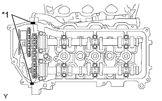
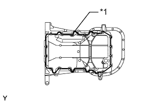
| 7. INSTALL OIL PAN SUB-ASSEMBLY |
Remove any old packing (FIPG) material and be careful not to drop any oil on the contact surfaces of the cylinder block, rear oil seal retainer and oil pan.
Install a new O-ring to the timing chain cover.
Apply seal packing in a continuous line as shown in the illustration.
- Seal packing:
- Toyota Genuine Seal Packing Black, Three Bond 1207B or equivalent
- Standard seal diameter:
- 3.0 to 4.0 mm (0.118 to 0.157 in.)
Text in Illustration *1 Seal Packing - NOTICE:
- Remove any oil from the contact surface.
- Install the oil pan within 3 minutes after applying seal packing. After installing the oil pan, the oil pan bolts and nuts must be tightened within 15 minutes. Otherwise the seal packing must be removed and reapplied.
- Do not start the engine for at least 2 hours after installing.
 |
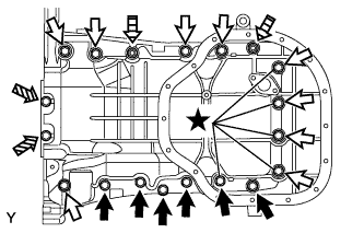
Install the oil pan with the 17 bolts and 2 nuts. Tighten the bolts and nuts uniformly in several steps.
- Torque:
- for bolt A and B, and nut:
- 21 N*m{214 kgf*cm, 15 ft.*lbf}
- for bolt C:
- 10 N*m{102 kgf*cm, 7 ft.*lbf}
- Standard Bolt:
Item Length Bolt A 25 mm (0.98 in.) Bolt B 45 mm (1.77 in.) Bolt C 14 mm (0.55 in.)
Text in Illustration Bolt A Bolt B Bolt C 
Nut - NOTICE:
- The bolts indicated by stars in the illustration are precoated parts. When reusing these bolts, apply adhesive to 2 or 3 threads before installation.
- Adhesive:
- Toyota Genuine Adhesive 1324, Three Bond 1324 or equivalent
 |
| 8. INSTALL OIL STRAINER SUB-ASSEMBLY |
Install a new gasket and the oil strainer with the bolt and 2 nuts.
- Torque:
- 9.0 N*m{92 kgf*cm, 80 in.*lbf}
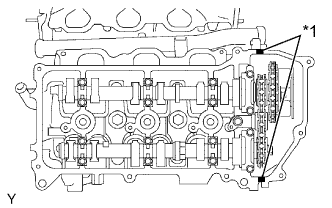
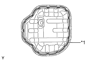
| 9. INSTALL NO. 2 OIL PAN SUB-ASSEMBLY |
Remove any old seal packing (FIPG) and be careful not to drop any oil on the contact surfaces of the oil pan and No. 2 oil pan.
Apply seal packing in a continuous line as shown in the illustration.
- Seal packing:
- Toyota Genuine Seal Packing Black, Three Bond 1207B or equivalent
- Standard seal diameter:
- 3.0 to 4.0 mm (0.118 to 0.157 in.)
Text in Illustration *1 Seal Packing - NOTICE:
- Remove any oil from the contact surface.
- Install the No. 2 oil pan within 3 minutes after applying seal packing. After installing the oil pan, the oil pan bolts and nuts must be tightened within 15 minutes. Otherwise the seal packing must be removed and reapplied.
- Do not start the engine for at least 4 hours after the installation.
 |
Install the No. 2 oil pan with the 14 bolts and 2 nuts. Tighten the bolts and nuts uniformly in several steps.
- Torque:
- for bolt:
- 9.0 N*m{92 kgf*cm, 80 in.*lbf}
- for nut:
- 10 N*m{102 kgf*cm, 7 ft.*lbf}
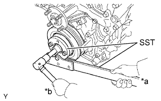
| 10. INSTALL CRANKSHAFT PULLEY |
Using SST, install the crankshaft pulley with the pulley set bolt.
- SST
- 09213-54015(91651-60855)
09330-00021
- Torque:
- 250 N*m{2549 kgf*cm, 184 ft.*lbf}
Text in Illustration *a Hold *b Turn
 |
| 11. INSTALL NO. 1 IDLER PULLEY SUB-ASSEMBLY |
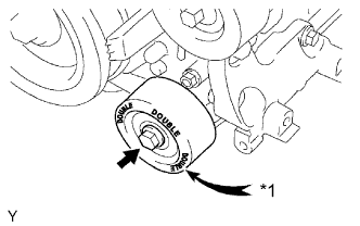 |
Install the No. 1 idler pulley with the bolt.
- Torque:
- 54 N*m{551 kgf*cm, 40 ft.*lbf}
Text in Illustration *1 "DOUBLE" - HINT:
- "DOUBLE" is marked on the No. 1 idler pulley to distinguish it from the No. 2 idler pulley.
| 12. INSTALL NO. 2 IDLER PULLEY SUB-ASSEMBLY |
w/ Idler Pulley Cover Plate:
Install the 2 idler pulley cover plates, 2 No. 2 idler pulleys and 2 No. 2 idler pulley cover plates with the 2 bolts.
- Torque:
- 54 N*m{551 kgf*cm, 40 ft.*lbf}
w/o Idler Pulley Cover Plate:
Install the 2 No. 2 idler pulleys and 2 No. 2 idler pulley cover plates with the 2 bolts.
- Torque:
- 54 N*m{551 kgf*cm, 40 ft.*lbf}
for Integrated Type:
Install the 2 No. 2 idler pulleys with the 2 bolts.
- Torque:
- 54 N*m{551 kgf*cm, 40 ft.*lbf}
| 13. INSTALL V-RIBBED BELT TENSIONER ASSEMBLY |
 |
Temporarily install the V-ribbed belt tensioner with the 5 bolts.
Install the V-ribbed belt tensioner by tightening bolt 1 and then bolt 2.
- Torque:
- 36 N*m{367 kgf*cm, 27 ft.*lbf}
Tighten the other bolts.
- Torque:
- 36 N*m{367 kgf*cm, 27 ft.*lbf}
- Bolt Length:
Bolt Length
mm (in.)A 70 mm (2.76 in.) B 33 mm (1.30 in.)
Text in Illustration Bolt A Bolt B
| 14. INSTALL WATER INLET ASSEMBLY |
Install a new O-ring to the water outlet pipe.
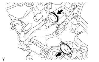 |
Install a new gasket to the water pump.
Apply soapy water to the O-ring.
Install the water inlet assembly to the 5 bolts.
- Torque:
- 9.0 N*m{92 kgf*cm, 80 in.*lbf}
Connect the 5 water by-pass hoses.
Install the 2 radiator hoses to the water inlet assembly.
| 15. INSTALL ENGINE OIL LEVEL DIPSTICK GUIDE |
Install a new O-ring to the engine oil level dipstick guide.
Text in Illustration *1 New O-Ring *a Push
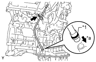 |
Apply a light coat of engine oil to the O-ring.
Push in the engine oil level dipstick guide end into the guide hole of the oil pan.
Install the engine oil level dipstick guide with the bolt.
- Torque:
- 9.0 N*m{92 kgf*cm, 80 in.*lbf}
Install the engine oil level dipstick.
| 16. INSTALL IGNITION COIL ASSEMBLY |
Install the 6 ignition coils with the 6 bolts.
- Torque:
- 10 N*m{102 kgf*cm, 7 ft.*lbf}
Connect the 6 ignition coil connectors.
| 17. INSTALL CAMSHAFT TIMING OIL CONTROL VALVE ASSEMBLY (for Bank 2) |
Apply a light coat of engine oil to a new O-ring of the camshaft timing oil control valve.
Install the camshaft timing oil control valve with the bolt.
- Torque:
- 10 N*m{102 kgf*cm, 7 ft.*lbf}
- NOTICE:
- Do not allow foreign matter to contact the oil seal face of the camshaft timing oil control valve (surface which contacts the cylinder head).
- Be careful that the O-ring is not cracked when installing the camshaft timing oil control valve.
Connect the camshaft timing oil control valve connector.
| 18. INSTALL CAMSHAFT TIMING OIL CONTROL VALVE ASSEMBLY (for Bank 1) |
Apply a light coat of engine oil to a new O-ring of the camshaft timing oil control valve.
Install the camshaft timing oil control valve with the bolt.
- Torque:
- 10 N*m{102 kgf*cm, 7 ft.*lbf}
- NOTICE:
- Do not allow foreign matter to contact the oil seal face of the camshaft timing oil control valve (surface which contacts the cylinder head).
- Be careful that the O-ring is not cracked when installing the camshaft timing oil control valve.
Connect the camshaft timing oil control valve connector.
| 19. INSTALL VVT SENSOR (for Bank 2) |
Apply a light coat of engine oil to the O-ring of the VVT sensor.
- NOTICE:
- When reusing the VVT sensor, inspect the O-ring.
- If the O-ring has scratches or cuts, replace the VVT sensor.
Install the VVT sensor with the bolt.
- Torque:
- 8.0 N*m{82 kgf*cm, 71 in.*lbf}
Connect the VVT sensor connector.
Connect the No. 4 and No. 5 water by-pass hoses.
| 20. INSTALL VVT SENSOR (for Bank 1) |
Apply a light coat of engine oil to the O-ring of the VVT sensor.
- NOTICE:
- When reusing the VVT sensor, inspect the O-ring.
- If the O-ring has scratches or cuts, replace the VVT sensor.
Install the VVT sensor with the bolt.
- Torque:
- 8.0 N*m{82 kgf*cm, 71 in.*lbf}
Connect the VVT sensor connector.
| 21. REMOVE ENGINE FROM ENGINE STAND |
Attach an engine sling device and hang the engine with a chain block
Lift the engine and remove it from the engine stand.
- NOTICE:
- With the exception of installing the engine assembly to an engine stand or removing the engine assembly from an engine stand, do not perform any work on the engine while it is suspended, as doing so is dangerous.
- Pay attention to the angle of the sling device as the engine assembly or engine hangers may be damaged or deformed if the angle is incorrect.
| 22. INSTALL ENGINE ASSEMBLY |