Dtc P20Cb Exhaust Aftertreatment Fuel Injector A Control Circuit Stuck Open
DESCRIPTION
MONITOR DESCRIPTION
WIRING DIAGRAM
INSPECTION PROCEDURE
INSPECT EXHAUST FUEL ADDITION INJECTOR ASSEMBLY (RESISTANCE)
CHECK TERMINAL VOLTAGE (POWER SOURCE)
CHECK HARNESS AND CONNECTOR (EXHAUST FUEL ADDITION INJECTOR ASSEMBLY - ECM)
REPLACE ECM
REPLACE EXHAUST FUEL ADDITION INJECTOR ASSEMBLY
REPAIR OR REPLACE HARNESS OR CONNECTOR
CONFIRM WHETHER MALFUNCTION HAS BEEN SUCCESSFULLY REPAIRED
DTC P20CB Exhaust Aftertreatment Fuel Injector "A" Control Circuit Stuck Open |
DTC P20CD Open in Exhaust Aftertreatment Fuel Injector "A" Control Circuit |
DTC P20CE Short in Exhaust Aftertreatment Fuel Injector "A" Control Circuit |
DESCRIPTION
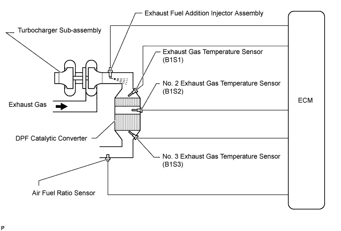
The exhaust fuel addition injector is mounted on the outlet of the turbocharger sub-assembly, and low pressure fuel is supplied to the injector by the feed pump in the supply pump. This injector adds fuel by a control signal from the ECM.This injector is used for two different controls: PM forced regeneration and PM reduction.During PM forced regeneration, the injector adds fuel to raise the catalyst temperature.In the other control, the injector helps the air-fuel ratio become rich. As a result, PM in the exhaust gas will be reduced in response to the rich air-fuel ratio.- HINT:
- For more information on the exhaust fuel addition injector and DPF, refer to the following procedures (HILUX_TGN26 RM000000XSN02CX.html).
- If P20CB, P20CD and P20CE are present, refer to the DTC table for Diesel Particulate Filter System (HILUX_TGN26 RM000000XSN02CX.html).
P20CBDTC Detection Drive Pattern
| DTC Detection Condition
| Trouble Area
|
Ignition switch ON for 3 seconds
| With the exhaust fuel addition injector off, the FIVM1 output is high and the FIVM2 output is low for 3 seconds.
(1 trip detection logic)
| - Open in exhaust fuel addition injector assembly circuit
- Exhaust fuel addition injector assembly
- ECM
|
P20CDDTC Detection Drive Pattern
| DTC Detection Condition
| Trouble Area
|
Ignition switch ON for 1 second
| With the exhaust fuel addition injector off, the FIVM1 output is high and the FIVM2 output is high for 0.16 seconds.
(1 trip detection logic)
| - Open in exhaust fuel addition injector assembly circuit
- Exhaust fuel addition injector assembly
- ECM
|
P20CEDTC Detection Drive Pattern
| DTC Detection Condition
| Trouble Area
|
Drive vehicle for 20 minutes (exhaust gas temperature is 250°C (482°F) or higher).
| With the exhaust fuel addition injector on, the FIVM1 output is low and the FIVM2 output is low 7 or more times.
(1 trip detection logic)
| - Open in exhaust fuel addition injector assembly circuit
- Exhaust fuel addition injector assembly
- ECM
|
- HINT:
- DTC P200C and/or P20CF will be present if there is an open malfunction in the exhaust fuel addition injector circuit.
MONITOR DESCRIPTION
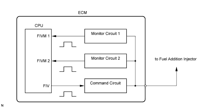
In order to detect abnormality in the fuel addition injector, an internal CPU of the ECM monitors injection command (FIV) signals and injection confirmation (FIVM) signals. The FIV signal is sent from the CPU to the exhaust fuel addition injector via a drive circuit inside the ECM. The FIVM signal, which is originally output current from the internal drive circuit of the ECM, is transmitted to the CPU via a monitor circuit. By receiving the FIVM signal, the ECM judges that the current has been applied to the exhaust fuel addition injector.This DTC will be set if the ECM judges that the number of signals of the FIV and FIVM are inconsistent.
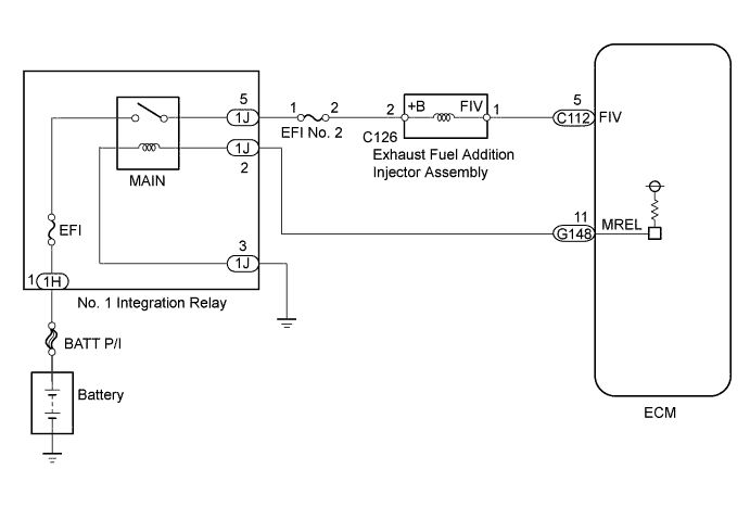
WIRING DIAGRAM
INSPECTION PROCEDURE
- NOTICE:
- Inspect the fuses of circuits related to this system before performing the following inspection procedure.
- After replacing the ECM, the new ECM needs registration (HILUX_TGN26 RM0000012XK070X.html) and initialization (HILUX_TGN26 RM000000TIN057X.html).
- After replacing the fuel supply pump assembly, the ECM needs initialization (HILUX_TGN26 RM000000TIN057X.html).
- After replacing an injector assembly, the ECM needs registration (HILUX_TGN26 RM0000012XK070X.html).
- HINT:
- Read freeze frame data using the intelligent tester. Freeze frame data records the engine condition when malfunctions are detected. When troubleshooting, freeze frame data can help determine if the vehicle was moving or stationary, if the engine was warmed up or not, and other data from the time the malfunction occurred.
| 1.INSPECT EXHAUST FUEL ADDITION INJECTOR ASSEMBLY (RESISTANCE) |
Inspect the exhaust fuel addition injector assembly (HILUX_TGN26 RM000003TI600IX.html).
| 2.CHECK TERMINAL VOLTAGE (POWER SOURCE) |
Disconnect the exhaust fuel addition injector assembly connector.
Measure the voltage according to the value(s) in the table below.
- Standard Voltage:
Tester Connection
| Switch Condition
| Specified Condition
|
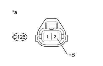
C126-2 (+B) - Body ground
| Ignition switch ON
| 11 to 14 V
|
Text in Illustration*a
| Front view of wire harness connector
(to Exhaust Fuel Addition Injector Assembly)
|
Reconnect the exhaust fuel addition injector assembly connector.
| 3.CHECK HARNESS AND CONNECTOR (EXHAUST FUEL ADDITION INJECTOR ASSEMBLY - ECM) |
Disconnect the exhaust fuel addition injector assembly connector.
Disconnect the ECM connector.
Measure the resistance according to the value(s) in the table below.
- Standard Resistance:
Tester Connection
| Condition
| Specified Condition
|
C126-1 (FIV) - C112-5 (FIV)
| Always
| Below 1 Ω
|
C126-1 (FIV) or C112-5 (FIV) - Body ground
| Always
| 10 kΩ or higher
|
Reconnect the exhaust fuel addition injector assembly connector.
Reconnect the ECM connector.
Replace the ECM (HILUX_TGN26 RM0000013Z001HX.html).
| 5.REPLACE EXHAUST FUEL ADDITION INJECTOR ASSEMBLY |
Replace the exhaust fuel addition injector assembly (HILUX_TGN26 RM000003TI800XX.html).
| 6.REPAIR OR REPLACE HARNESS OR CONNECTOR |
- HINT:
- If the voltage at the exhaust fuel addition injector assembly connector is not 11 to 14 V, repair or replace the harness and connector between the exhaust fuel addition injector assembly and EFI MAIN relay (including the EFI No. 2 fuse).
Repair or replace the harness or connector.
| 7.CONFIRM WHETHER MALFUNCTION HAS BEEN SUCCESSFULLY REPAIRED |
Connect the intelligent tester to the DLC3.
Clear the DTCs (HILUX_TGN26 RM000000PDK11ZX.html).
Drive the vehicle for 20 minutes.
- HINT:
- The exhaust gas temperature increases to 250°C (482°F) or higher after driving the vehicle for 20 minutes.
Enter the following menus: Powertrain / Engine and ECT / DTC.
Confirm that the DTC is not output again.