Ecd System (For Dpf) -- System Description |
| ENGINE CONTROL SYSTEM |
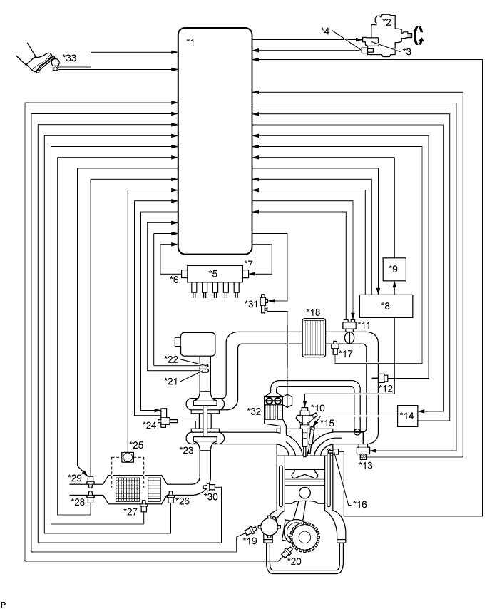
| *1 | ECM | *2 | Fuel Supply Pump Assembly |
| *3 | Suction Control Valve | *4 | Fuel Temperature Sensor |
| *5 | Common Rail Assembly | *6 | Fuel Pressure Sensor |
| *7 | Pressure Discharge Valve | *8 | Injector Driver |
| *9 | EDU Relay | *10 | Injector Assembly |
| *11 | Diesel Throttle Body Assembly | *12 | Manifold Absolute Pressure Sensor |
| *13 | Electric EGR Control Valve Assembly | *14 | Glow Plug Controller |
| *15 | Glow Plug | *16 | Engine Coolant Temperature Sensor |
| *17 | Intake Air Temperature Sensor (Turbo) | *18 | Intercooler |
| *19 | Camshaft Position Sensor | *20 | Crankshaft Position Sensor |
| *21 | Mass Air Flow Meter | *22 | Intake Air Temperature Sensor (Built Into Mass Air Flow Meter) |
| *23 | Turbocharger Sub-assembly | *24 | DC motor, Nozzle Vane Position Sensor |
| *25 | Differential Pressure Sensor Assembly | *26 | Exhaust Gas Temperature Sensor (B1S1) |
| *27 | No. 2 Exhaust Gas Temperature Sensor (B1S2) | *28 | No. 3 Exhaust Gas Temperature Sensor (B1S3) |
| *29 | Air Fuel Ratio Sensor | *30 | Exhaust Fuel Addition Injector Assembly |
| *31 | VSV for EGR Bypass Valve | *32 | EGR Cooler |
| *33 | Accelerator Pedal Position Sensor | - | - |
| DIESEL PARTICULATE FILTER SYSTEM DESCRIPTION |
Diesel Particulate Filter System comprehensively regulates engine control (consists of a catalytic system and a fuel injection system) that purifies particulate matter (PM) by diesel engines. The catalytic system purifies hydrocarbons (HC) and carbon monoxides (CO), and reduces PM with a catalytic converter with the Diesel Particulate Filter (DPF). The fuel injection system adds fuel into the exhaust port using the exhaust fuel addition injector to produce maintain a proper catalyst temperature for PM forced regeneration.
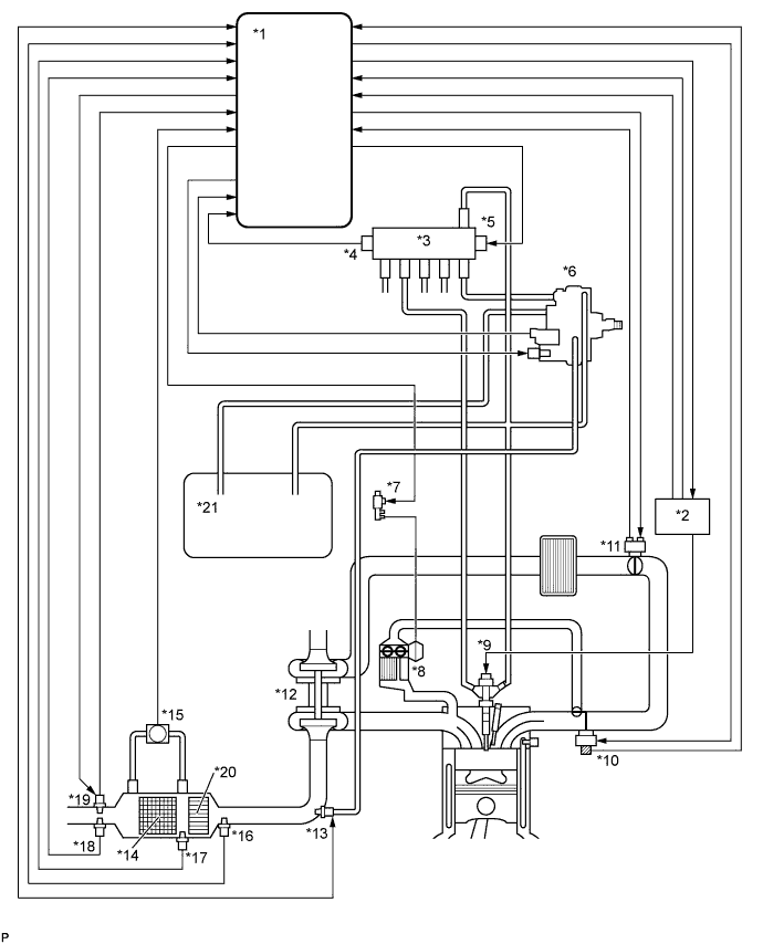
Text in Illustration *1 ECM *2 Injector Driver *3 Common Rail Assembly *4 Fuel Pressure Sensor *5 Pressure Discharge Valve *6 Fuel Supply Pump Assembly *7 VSV for EGR Bypass Valve *8 EGR Cooler *9 Injector Assembly *10 Electric EGR Control Valve Assembly *11 Diesel Throttle Body Assembly *12 Turbocharger Sub-assembly *13 Exhaust Fuel Addition Injector Assembly *14 DPF Catalytic Converter *15 Differential Pressure Sensor Assembly *16 Exhaust Gas Temperature Sensor (B1S1) *17 No. 2 Exhaust Gas Temperature Sensor (B1S2) *18 No. 3 Exhaust Gas Temperature Sensor (B1S3) *19 Air Fuel Ratio Sensor *20 CCo Catalyst Converter *21 Fuel Tank - - DPF components:
Component Description DPF catalytic converter Reduces HC, CO and PM. Exhaust Fuel Addition Injector Assembly Adds fuel into the exhaust port in order to raise catalyst temperature for PM forced regeneration. Exhaust gas temperature sensor Used for estimating the DPF catalytic converter temperature and adjusting fuel addition by ECM while PM forced regeneration is performed. Also detects the DPF catalytic converter temperature to prevent the catalytic converter temperature from rising too high. Differential Pressure Sensor Assembly Detects the volume of PM deposits and any incorrect vacuum hose arrangement on the DPF catalytic converter. Air fuel ratio sensor Used for controlling the air-fuel ratio. By controlling the air-fuel ratio, combustion control and PM forced regeneration are properly regulated. Diagnostics Trouble Codes (DTCs) table for DPF:
- HINT:
- This table indicates typical DTC combinations for each malfunction occurrence.
*: There may be no DTC output depending on the condition of the malfunction.Trouble Area Malfunction DTC No. DPF catalytic converter Deteriorated or clogged P062F, P2002, P200C*, P244A*, P244B*, P244C*, P2463* Exhaust Fuel Addition Injector Assembly Stuck open P20CF Stuck closed P244A*, P244C Low fuel addition volume P244A*, P244B*, P244C*, P2463 Open in exhaust fuel addition injector circuit P20CB, P244A*, P244C Short in exhaust fuel addition injector circuit P20CF, P20CB, P244A*, P244C Open or short in exhaust fuel addition injector circuit P200C*, P20CF*, P20CB, P244A*, P244A*, P244C* Exhaust gas temperature sensor Open in exhaust gas temperature sensor circuit P0545, P0546, P200C*, P2032, P2033, P2084, P242B, P242C, P242D, P244C* Short in exhaust gas temperature sensor circuit P0545, P0546, P200C*, P2002*, P2032, P2033, P2084, P242B, P242C, P242D, P244C* Exhaust gas temperature sensor P0545, P0546, P200C*, P2032, P2033, P2084, P242B, P242C, P242D, P244C* Differential Pressure Sensor Assembly Open in differential pressure sensor circuit P244A*, P244C* P2454, P2455, P2463* Short in differential pressure sensor circuit P244A*, P244C*, P2454, P2455, P2463* Differential pressure sensor P244A*, P244C*, P2454, P2455, P2463* Differential pressure sensor clogged P244A*, P244C*, P2453, P2463* Incorrect vacuum hose arrangement of the differential pressure sensor P244A*, P244C*, P2453, P2463* Air fuel ratio sensor Open or short in air fuel ratio sensor or heater circuit P0031, P0032, P2238, P2239, P2252, P2253, P244B*, P2463* Air fuel ratio sensor P0031, P0032, P2195, P2238, P2239, P2252, P2253, P244B*, P2463* Exhaust gas leaks Exhaust gas leaks P244A*, P244C* Fuel leaks Fuel leaks in fuel addition injector P2002*, P200C*, P20CF*, P244A*, P244B*, P244C*, P2463* Fuel supply pump assembly Correct fuel pressure cannot be fed to the exhaust fuel addition injector P244A*, P244B*, P244C*, P2463* Diagnostics trouble code description for DPF:
DTC No. Description P0031 Open in air fuel ratio sensor heater control circuit (Low output) P0032 Short in air fuel ratio sensor or heater circuit (High output) P0545 Open or short in exhaust gas temperature sensor circuit (B1S1) (Low output) P0546 Open or short in exhaust gas temperature sensor circuit (B1S1) (High output) P2002 DPF catalytic converter thermal deterioration P200C DPF catalytic converter abnormally high exhaust gas temperature P2032 Open or short in exhaust gas temperature sensor circuit (B1S2) (Low output) P2033 Open or short in exhaust gas temperature sensor circuit (B1S2) (High output) P2084 Exhaust Gas Temperature Sensor Circuit Range/Performance (B1S2) P20CB Open in exhaust fuel addition injector circuit P20CF Exhaust fuel addition injector assembly stuck open P2195 Air fuel ratio sensor stuck lean P2238 Open or short in air fuel ratio sensor or heater circuit (Low output) P2239 Open or short in air fuel ratio sensor or heater circuit (High output) P2252 Open or short in air fuel ratio sensor or heater circuit (Low output) P2253 Open or short in air fuel ratio sensor or heater circuit (High output) P242B Exhaust Gas Temperature Sensor Circuit Range / Performance (B1S3) P242C Open or short in exhaust gas temperature sensor circuit (B1S3) (Low output) P242D Open or short in exhaust gas temperature sensor circuit (B1S3) (High output) P244A DPF catalytic converter excessive differential pressure (Low input) P244B DPF catalytic converter excessive differential pressure (High input) P244C DPF catalytic converter insufficient temperature increase P2453 Differential pressure sensor is clogged or has incorrect vacuum hose arrangement P2454 Open or short in differential pressure sensor circuit (Low output) P2455 Open or short in differential pressure sensor circuit (High output) P2463 DPF catalytic converter soot deposition
| COMMON RAIL SYSTEM DESCRIPTION |
Common rail system:
The common rail system uses high-pressure fuel for improved fuel economy. This system also provides robust engine power while suppressing engine vibration and noise.
This system stores fuel in the common rail, which has been pressurized and supplied by the fuel supply pump. By storing fuel at high-pressure, the common rail system can provide fuel at stable fuel injection pressures, regardless of engine speed or engine load.
The ECM, using the injector driver, provides an electric current to the piezo actuator in each injector to regulate the fuel injection timing and volume. The ECM also monitors the internal fuel pressure of the common rail using the fuel pressure sensor. The ECM causes the fuel supply pump to supply the fuel necessary to obtain the target fuel pressure.
In addition, this system uses a piezo actuator inside each injector to open and close the fuel passages. Therefore, both fuel injection time and fuel injection volume can be precisely regulated by the ECM.
The common rail system allows a two stage fuel injection process. In order to soften combustion shock, this system performs "pilot-injection" prior to the main fuel injection. This helps to reduce engine vibration and noise.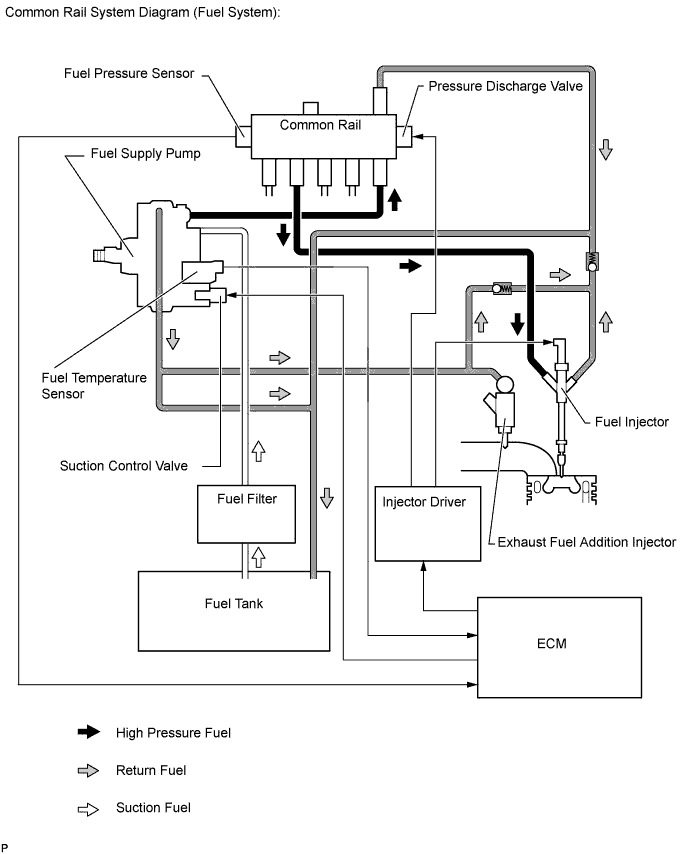
- HINT:
- If there is a problem with a fuel return pipe, as bleeding air from the fuel system may not be able to be performed properly in certain instances, such as after replacing a fuel injector, etc., the engine startability may deteriorate.
Common rail system components:
Component Description Common rail assembly Stores high-pressure fuel produced by supply pump Fuel supply pump assembly - Operated by crankshaft via gear
- Supplies high-pressure fuel to common rail
Injector assembly Injects fuel to combustion chamber based on signals from ECM Fuel pressure sensor Monitors internal fuel pressure of common rail and sends signals to ECM Pressure discharge valve Based on signals from ECM, opens valve when sudden deceleration occurs, or when ignition switch is off to prevent fuel pressure from becoming too high. Suction control valve Based on signals from ECM, adjusts fuel volume supplied to common rail and regulates internal fuel pressure Check valve Keeps pressure that discharges from injector - Operated by crankshaft via gear
Diagnostic trouble code (DTC) table for the common rail system:
- HINT:
- This table indicates typical DTC combinations for each malfunction occurrence.
*: There may be no DTC output depending on the condition of the malfunction.Trouble Area Malfunction DTC No. Injector assembly Open or short in injector circuit P0093*, P0201, P0202, P0203, P0204, P062D Stuck open P0093 Stuck closed P0301, P0302, P0303, P0304 Fuel pressure sensor Open or short in fuel pressure sensor circuit or pressure sensor output fixed P0087, P0190, P0191, P0192, P0193 Pressure discharge valve Open or short in pressure discharge valve circuit P0088*, P0093*, P1229*, P1271, P1272 Stuck open P0093 Stuck closed P0088*, P1272 Suction control valve Open or short in suction control valve circuit P0627, P1229, P0088* Stuck open P0088*, P1229 Injector driver Faulty injector driver P0093*, P0201*, P0202*, P0203*, P0204*, P062D*, P1271*, P1272* Common rail system (Fuel system) Fuel leaks in high-pressure area P0093 Diagnostic trouble code description for the common rail system:
DTC No. Description P0087 Fuel pressure sensor output does not change P0088 Internal fuel pressure too high (220000 kPa [2243 kgf/cm2, 31900 psi] or more) P0093 Fuel leaks in high-pressure areas P0190 Open or short in fuel pressure sensor circuit (output voltage is too low or too high) P0192 Open or short in fuel pressure sensor circuit (output voltage is too low) P0193 Open or short in fuel pressure sensor circuit (output voltage is too high) P0201 Open or short in No. 1 injector circuit P0202 Open or short in No. 2 injector circuit P0203 Open or short in No. 3 injector circuit P0204 Open or short in No. 4 injector circuit P0301 Cylinder 1 misfire detected P0302 Cylinder 2 misfire detected P0303 Cylinder 3 misfire detected P0304 Cylinder 4 misfire detected P0627 Open or short in suction control valve circuit P062D Open or short in injector driver or injector circuit P1229 Fuel over-feed P1271 Open or short in pressure discharge valve circuit P1272 Pressure discharge valve stuck close
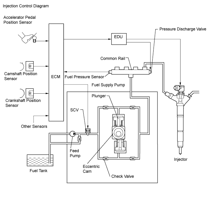
| INJECTION CONTROL SYSTEM DESCRIPTION |
The ECM determines the injection volume and injection timing based on signals from the accelerator pedal position sensor, crankshaft position sensor and camshaft position sensor. Based on the signals from the ECM, the injector driver controls the injectors. The injector driver also controls the suction control valve installed on the fuel supply pump to help regulate fuel pressure.
The piezo type injector used in the 2KD-FTV engine makes noise when the engine is idling because this injector operates at high speed. Therefore, the injector driver controls the injector to operate at low speed when the engine is idling based on signals from the ECM to achieve noise reduction.
The feed pump is used to pump fuel from the fuel tank to the fuel supply pump assembly.
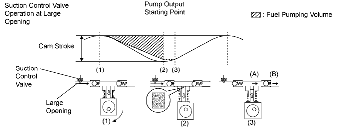
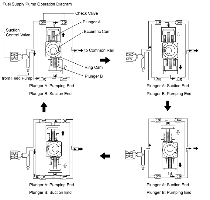
| FUEL SUPPLY PUMP OPERATION SYSTEM DESCRIPTION |
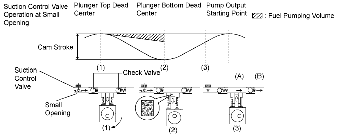
| SUCTION CONTROL VALVE OPERATION SYSTEM DESCRIPTION |
- HINT:
- The ECM controls the suction control valve operation to regulate the fuel volume that is produced by the fuel supply pump for the common rail. This control is performed to regulate the internal fuel pressure of the common rail to the target injection pressure.
Small opening of the suction control valve:
When the opening of the suction control valve is small, the volume of supplied fuel is small.
The suction volume becomes small due to the narrow path despite the plunger stroke being full. The difference between the geometrical volume and suction volume creates a vacuum.
Pump output will start when the fuel pressure at (A) becomes higher than the common rail pressure (B).
Large opening of the suction control valve:
When the opening of the suction control valve is large, the volume of supplied fuel is large.
If the plunger stroke is full, the suction volume becomes large because of the wide path.
Pump output will start when the fuel pressure at (A) becomes higher than the common rail pressure (B).