Steering Gear -- Removal |
| 1. REMOVE FRONT WHEELS |
| 2. REMOVE NO. 2 ENGINE UNDER COVER |
Remove the 4 bolts and under cover.
| 3. REMOVE NO. 1 ENGINE UNDER COVER |
Remove the 4 bolts and under cover.
| 4. REMOVE FRONT SIDE MEMBER TO FRONT SUSPENSION CROSSMEMBER BRACE |
Remove the 10 bolts and 2 crossmember braces.
| 5. REMOVE FRONT STABILIZER BAR |
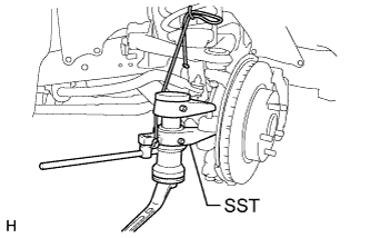
| 6. DISCONNECT TIE ROD END SUB-ASSEMBLY LH |
Remove the cotter pin and nut.
Using SST, disconnect the tie rod end from the steering knuckle arm.
- SST
- 09628-00011
 |
| 7. DISCONNECT TIE ROD END SUB-ASSEMBLY RH |
- HINT:
- Use the same procedure described for the LH side.
| 8. DISCONNECT STEERING SLIDING YOKE |
Loosen the bolt labeled A.
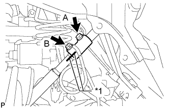 |
Place matchmarks on the steering sliding yoke and steering intermediate shaft.
Text in Illustration *1 Matchmark
Remove the bolt labeled B.
Disconnect the steering sliding yoke from the steering intermediate shaft.
 |
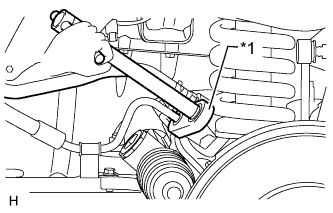
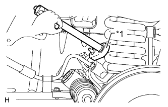
| 9. REMOVE NO. 2 STEERING INTERMEDIATE SHAFT SUB-ASSEMBLY |
Place matchmarks on the intermediate shaft and steering link.
Text in Illustration *1 Matchmark
 |
Remove the bolt.
 |
Remove the intermediate shaft from the steering link.
| 10. DISCONNECT PRESSURE FEED TUBE ASSEMBLY |
Using a union nut wrench, loosen the flare nut and disconnect the pressure feed tube.
Text in Illustration *1 Union Nut Wrench
 |
Remove the bolt and disconnect the pressure feed tube from the steering link.
 |
| 11. DISCONNECT STEERING GEAR OUTLET RETURN TUBE |
Detach the clip and disconnect the return hose.
 |
Using a union nut wrench, disconnect the outlet return tube.
Text in Illustration *1 Union Nut Wrench
 |
| 12. REMOVE POWER STEERING LINK ASSEMBLY |
Fix the 2 nuts in place and remove the 2 bolts. Then remove the link from the frame.
- NOTICE:
- Never turn the nut. Be sure to turn the bolt.
- HINT:
- Removal of the link may be easier if the following is performed: 1) remove the differential mount, and 2) slide the differential toward the rear of the vehicle.
 |