Brake. Hilux. Tgn26, 36 Kun25, 26, 35, 36 Ggn25
DESCRIPTION
WIRING DIAGRAM
INSPECTION PROCEDURE
CHECK HARNESS AND CONNECTOR (MOMENTARY INTERRUPTION)
READ VALUE USING INTELLIGENT TESTER (RR/RL WHEEL SPEED)
PERFORM TEST MODE (SIGNAL CHECK)
RECONFIRM DTC
CHECK THAT SKID CONTROL ECU AND REAR SPEED SENSOR CONNECTORS ARE SECURELY CONNECTED
RECONFIRM DTC
CHECK REAR SPEED SENSOR INSTALLATION
INSPECT REAR SPEED SENSOR TIP
INSPECT REAR SPEED SENSOR
CHECK HARNESS AND CONNECTOR (SKID CONTROL ECU - REAR SPEED SENSOR)
INSPECT REAR SKID CONTROL ROTOR
REPLACE REAR SPEED SENSOR
CONFIRM DTC
DTC C0210/33 Rear Speed Sensor RH Circuit |
DTC C0215/34 Rear Speed Sensor LH Circuit |
DTC C1238/38 Foreign Object is Attached on Tip of Rear Speed Sensor RH |
DTC C1239/39 Foreign Object is Attached on Tip of Rear Speed Sensor LH |
DTC C1273/73 Low Output Signal of Rear Speed Sensor RH (Test Mode DTC) |
DTC C1274/74 Low Output Signal of Rear Speed Sensor LH (Test Mode DTC) |
DTC C1277/77 Abnormal Change in Output Signal of Rear Speed Sensor RH (Test Mode DTC) |
DTC C1278/78 Abnormal Change in Output Signal of Rear Speed Sensor LH (Test Mode DTC) |
DESCRIPTION
The speed sensors detect the wheel speeds and send appropriate signals to the skid control ECU (brake actuator assembly). These signals are used for control of the ABS.Each of the front and rear rotors have 48 serrations. When the rotors rotate, the magnetic field generated by the permanent magnet in the speed sensor produces AC voltage. Since the frequency of this AC voltage changes in direct proportion to the speed of the rotor, the frequency is used by the skid control ECU (brake actuator assembly) to detect the speed of each wheel.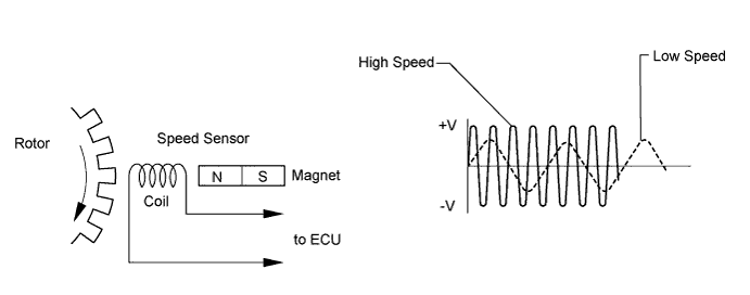
DTC Code
| DTC Detection Condition
| Trouble Area
|
C0210/33
C0215/34
| One of the following conditions is met:
- At a vehicle speed of 10 km/h (6 mph) or more, an open or short in the sensor signal circuit continues for 15 seconds or more.
- Momentary interruption of the sensor signal from the abnormal wheel occurs 7 times or more.
- An open in the speed sensor signal circuit continues for 0.5 seconds or more.
| - Rear speed sensor RH/LH
- Rear speed sensor circuit
- Rear skid control rotor RH/LH
- Sensor installation
- Skid control ECU (Brake actuator assembly)
|
C1238/38
C1239/39
| At a vehicle speed of 20 km/h (12 mph) or more, condition that noise is included in speed sensor signal continues for 5 seconds or more.
| - Rear speed sensor RH/LH
- Rear speed sensor circuit
- Sensor installation
|
C1273/73
C1274/74
| Detected only during Test Mode.
| - Rear speed sensor RH/LH
- Sensor installation
- Rear skid control rotor RH/LH
|
C1277/77
C1278/78
| Detected only during Test Mode.
| Rear skid control rotor RH/LH
|
- HINT:
- DTCs C0210/33, C1238/38, C1273/73 and C1277/77 are for the rear speed sensor RH.
- DTCs C0215/34, C1239/39, C1274/74 and C1278/78 are for the rear speed sensor LH.
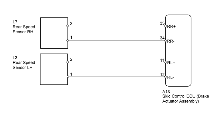
WIRING DIAGRAM
INSPECTION PROCEDURE
- NOTICE:
- Check the speed sensor signal after cleaning or replacement (HILUX_TGN26 RM000000XHT090X.html).
- Before disconnecting the connector, make sure that there are no problems with the connection.
- After disconnecting the connector, make sure that the connector case and terminals are not deformed or corroded.
| 1.CHECK HARNESS AND CONNECTOR (MOMENTARY INTERRUPTION) |
Using the intelligent tester, check for any momentary interruptions in the wire harness and connector corresponding to the DTC (HILUX_TGN26 RM000000XHS0AFX.html).
ABS/VSC/TRCTester Display
| Measurement Item/Range
| Normal Condition
| Diagnostic Note
|
RR Speed Open
| Rear speed sensor RH open circuit detection/ Opn_Det or Normal
| Normal
| -
|
RL Speed Open
| Rear speed sensor LH open circuit detection/ Opn_Det or Normal
| Normal
| -
|
- OK:
- Normal (There are no momentary interruptions.)
- HINT:
- Perform the above inspection before removing the sensor and connector.
| 2.READ VALUE USING INTELLIGENT TESTER (RR/RL WHEEL SPEED) |
Turn the ignition switch off.
Connect the intelligent tester to the DLC3.
Turn the intelligent tester on.
Start the engine.
Enter the following menus: Chassis / ABS/VSC/TRC / Data List, and then drive the vehicle.
ABS/VSC/TRCTester Display
| Measurement Item/Range
| Normal Condition
| Diagnostic Note
|
RR Wheel Speed
| Rear speed sensor RH reading/
Min.: 0 km/h (0 mph)
Max.: 326 km/h (202 mph)
| Actual wheel speed
| No large fluctuations when driving at a constant speed.
|
RL Wheel Speed
| Rear speed sensor LH reading/
Min.: 0 km/h (0 mph)
Max.: 326 km/h (202 mph)
| Actual wheel speed
| No large fluctuations when driving at a constant speed.
|
Check the speed value output from the speed sensor displayed on the intelligent tester.
- HINT:
- Factors that affect the indicated vehicle speed include tire size, tire inflation and tire wear. The speed indicated on the speedometer has an allowable margin of error. This can be tested using a speedometer tester (calibrated chassis dynamometer). For details about testing and the margin of error, see the reference chart (HILUX_TGN26 RM000002Z4Q01WX.html).
- OK:
- The speed value output from the speed sensor displayed on the intelligent tester is the same as the actual vehicle speed measured using a speedometer tester (calibrated chassis dynamometer).
| 3.PERFORM TEST MODE (SIGNAL CHECK) |
Perform the sensor check in the Test Mode procedure (HILUX_TGN26 RM000000XHT090X.html).
- OK:
- All Test Mode DTCs are cleared.
Clear the DTC (HILUX_TGN26 RM000000XHV0CFX.html).
Turn the ignition switch off.
Start the engine.
Drive the vehicle at a speed of 20 km/h (12 mph) or more for at least 60 seconds.
Check if the same DTC is output (HILUX_TGN26 RM000000XHV0CFX.html).
ResultResult
| Proceed to
|
DTC not output
| A
|
DTC output
| B
|
- HINT:
- If troubleshooting has been carried out according to the problem symptoms table, refer back to the table and proceed to the next step (HILUX_TGN26 RM000000XHN0CQX.html).
| 5.CHECK THAT SKID CONTROL ECU AND REAR SPEED SENSOR CONNECTORS ARE SECURELY CONNECTED |
Check that the skid control ECU (brake actuator assembly) and the rear speed sensor connectors are securely connected.
Clear the DTC (HILUX_TGN26 RM000000XHV0CFX.html).
Turn the ignition switch off.
Start the engine.
Drive the vehicle at a speed of 20 km/h (12 mph) or more for at least 60 seconds.
Check if the same DTC is output (HILUX_TGN26 RM000000XHV0CFX.html).
ResultResult
| Proceed to
|
DTC output
| A
|
DTC not output
| B
|
| 7.CHECK REAR SPEED SENSOR INSTALLATION |
Turn the ignition switch off.
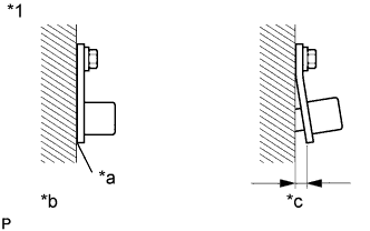
Check the rear speed sensor installation (HILUX_TGN26 RM0000010JQ029X.html).
- OK:
- The installation bolt is tightened properly.
There is no clearance between the sensor and rear axle housing.
Text in Illustration*1
| Rear Speed Sensor
|
*a
| No clearance
|
*b
| CORRECT
|
*c
| INCORRECT
|
| | INSTALL REAR SPEED SENSOR CORRECTLY |
|
|
| 8.INSPECT REAR SPEED SENSOR TIP |
Turn the ignition switch off.
Remove the rear speed sensor (HILUX_TGN26 RM0000010JT01XX.html).
Check the speed sensor tip.
- OK:
- No scratches, oil or foreign matter on the sensor tip.
- NOTICE:
- Do not replace the speed sensor if no damage to the speed sensor tip is found.
- HINT:
- If the sensor is contaminated with oil or other foreign material, clean the sensor.
- If there is iron powder sticking to the rotor, this will result in a malfunction. Confirm that the rotor is not contaminated with foreign material before replacing the sensor.
| | CLEAN OR REPLACE REAR SPEED SENSOR |
|
|
| 9.INSPECT REAR SPEED SENSOR |
Turn the ignition switch off.
Remove the rear speed sensor (HILUX_TGN26 RM0000010JT01XX.html).
Inspect the rear speed sensor (HILUX_TGN26 RM0000010JR01AX.html).
| 10.CHECK HARNESS AND CONNECTOR (SKID CONTROL ECU - REAR SPEED SENSOR) |
Turn the ignition switch off.
Disconnect the skid control ECU (brake actuator assembly) connector.
Disconnect the rear speed sensor connector.
Measure the resistance according to the value(s) in the table below.
- Standard Resistance:
- for LH:
Tester Connection
| Condition
| Specified Condition
|
A13-11 (RL+) - L3-2
| Always
| Below 1 Ω
|
A13-11 (RL+) - Body ground
| Always
| 10 kΩ or higher
|
A13-12 (RL-) - L3-1
| Always
| Below 1 Ω
|
A13-12 (RL-) - Body ground
| Always
| 10 kΩ or higher
|
- for RH:
Tester Connection
| Condition
| Specified Condition
|
A13-33 (RR+) - L7-2
| Always
| Below 1 Ω
|
A13-33 (RR+) - Body ground
| Always
| 10 kΩ or higher
|
A13-34 (RR-) - L7-1
| Always
| Below 1 Ω
|
A13-34 (RR-) - Body ground
| Always
| 10 kΩ or higher
|
| | REPAIR OR REPLACE HARNESS OR CONNECTOR |
|
|
| 11.INSPECT REAR SKID CONTROL ROTOR |
Turn the ignition switch off.
Remove the rear axle shaft with backing plate (HILUX_TGN26 RM000000ZZV01EX.html).
Check the rear skid control rotor.
- OK:
- No scratches, oil or foreign matter on the rotors.
| | CLEAN OR REPLACE REAR SKID CONTROL ROTOR |
|
|
| 12.REPLACE REAR SPEED SENSOR |
Turn the ignition switch off.
Replace the rear speed sensor (HILUX_TGN26 RM0000010JT01XX.html).
Clear the DTC (HILUX_TGN26 RM000000XHV0CFX.html).
Turn the ignition switch off.
Start the engine.
Drive the vehicle at a speed of 20 km/h (12 mph) or more for at least 60 seconds.
Check if the same DTC is output (HILUX_TGN26 RM000000XHV0CFX.html).
ResultResult
| Proceed to
|
DTC output
| A
|
DTC not output
| B
|