Ecd System (For Dpf) Ecm Power Source Circuit
DESCRIPTION
WIRING DIAGRAM
INSPECTION PROCEDURE
INSPECT ECM (+B AND +B2 VOLTAGE)
CHECK HARNESS AND CONNECTOR (ECM - BODY GROUND)
INSPECT ECM (IGSW VOLTAGE)
INSPECT ECM (MREL VOLTAGE)
INSPECT NO. 1 INTEGRATION RELAY (MAIN RELAY)
CHECK HARNESS AND CONNECTOR (MAIN RELAY - ECM, MAIN RELAY - BODY GROUND)
INSPECT IGNITION SWITCH
ECD SYSTEM (for DPF) - ECM Power Source Circuit |
DESCRIPTION
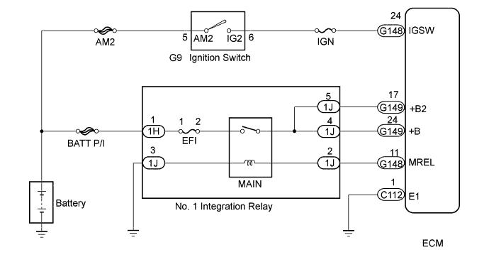
When the ignition switch is turned to ON, the battery voltage is applied to terminal IGSW of the ECM. The MREL output signal from ECM causes a current to flow to the coil, closing the contacts of the MAIN relay and supplying power to terminal +B of the ECM.
WIRING DIAGRAM
INSPECTION PROCEDURE
- NOTICE:
- After replacing the ECM, the new ECM needs registration (HILUX_TGN26 RM0000012XK07EX.html) and initialization (HILUX_TGN26 RM000000TIN056X.html).
- Inspect the fuses of circuits related to this system before performing the following inspection procedure.
| 1.INSPECT ECM (+B AND +B2 VOLTAGE) |
Turn the ignition switch to ON.
Measure the voltage according to the value(s) in the table below.
- Standard Voltage:
Tester Connection
| Condition
| Specified Condition
|
G149-24 (+B) - C112-1 (E1)
| Ignition switch ON
| 11 to 14 V
|
G149-17 (+B2) - C112-1 (E1)
| Ignition switch ON
| 11 to 14 V
|
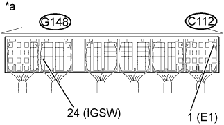
Text in Illustration*a
| Component with harness connected
(ECM)
|
| 2.CHECK HARNESS AND CONNECTOR (ECM - BODY GROUND) |
Disconnect the ECM connector.
Measure the resistance according to the value(s) in the table below.
- Standard Resistance:
Tester Connection
| Condition
| Specified Condition
|
C112-1 (E1) - Body ground
| Always
| Below 1 Ω
|
Reconnect the ECM connector.
| | REPAIR OR REPLACE HARNESS OR CONNECTOR |
|
|
| 3.INSPECT ECM (IGSW VOLTAGE) |
Turn the ignition switch to ON.
Measure the voltage according to the value(s) in the table below.
- Standard Voltage:
Tester Connection
| Switch Condition
| Specified Condition
|
G148-24 (IGSW) - C112-1 (E1)
| Ignition switch ON
| 11 to 14 V
|
Text in Illustration*a
| Component with harness connected
(ECM)
|
| 4.INSPECT ECM (MREL VOLTAGE) |
Turn the ignition switch to ON.
Measure the voltage according to the value(s) in the table below.
- Standard Voltage:
Tester Connection
| Switch Condition
| Specified Condition
|
G148-11 (MREL) - C112-1 (E1)
| Ignition switch ON
| 11 to 14 V
|
Text in Illustration*a
| Component with harness connected
(ECM)
|
| 5.INSPECT NO. 1 INTEGRATION RELAY (MAIN RELAY) |
Inspect the No. 1 integration relay (MAIN relay) (HILUX_TGN26 RM00000469100QX_01_0004.html).
| | REPLACE INTEGRATION NO. 1 RELAY (MAIN RELAY) |
|
|
| 6.CHECK HARNESS AND CONNECTOR (MAIN RELAY - ECM, MAIN RELAY - BODY GROUND) |
Check the harness and connector between the No. 1 integration relay (MAIN relay) and ECM.
Remove the No. 1 integration relay from the engine room relay block and junction block assembly.
Disconnect the ECM connector.
Measure the resistance according to the value(s) in the table below.
- Standard Resistance:
Tester Connection
| Condition
| Specified Condition
|
1J-4 - G149-24 (+B)
| Always
| Below 1 Ω
|
1J-5 - G149-17 (+B2)
| Always
| Below 1 Ω
|
1J-2 - G148-11 (MREL)
| Always
| Below 1 Ω
|
1J-4 or G149-24 (+B) - Body ground
| Always
| 10 kΩ or higher
|
1J-5 or G149-17 (+B2) - Body ground
| Always
| 10 kΩ or higher
|
1J-2 or G148-11 (MREL) - Body ground
| Always
| 10 kΩ or higher
|
Reconnect the ECM connector.
Reinstall the No. 1 integration relay.
Check the harness and connector between the No. 1 integration relay (MAIN relay) and body ground.
Remove the No. 1 integration relay from the engine room relay block and junction block assembly.
Measure the resistance according to the value(s) in the table below.
- Standard Resistance:
Tester Connection
| Condition
| Specified Condition
|
1J-3 - Body ground
| Always
| Below 1 Ω
|
Reinstall the No. 1 integration relay.
| | REPAIR OR REPLACE HARNESS OR CONNECTOR |
|
|
| OK |
|
|
|
| REPAIR OR REPLACE HARNESS OR CONNECTOR (BATTERY - MAIN RELAY) |
|
| 7.INSPECT IGNITION SWITCH |
Inspect the ignition switch (HILUX_TGN26 RM0000013ZU019X.html).
| OK |
|
|
|
| REPAIR OR REPLACE HARNESS OR CONNECTOR (BATTERY - IGNITION SWITCH, IGNITION SWITCH - ECM) |
|