Dtc B156C Extension Module Disconnected
DESCRIPTION
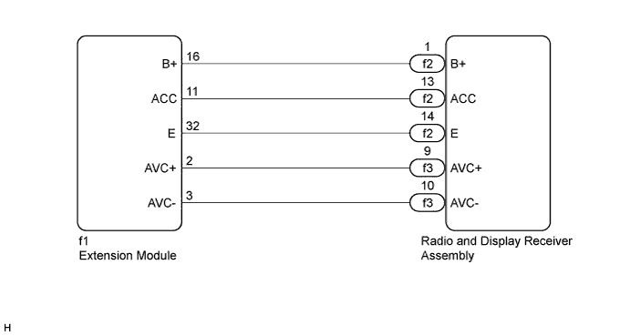
WIRING DIAGRAM
INSPECTION PROCEDURE
CHECK OPTIONAL COMPONENTS (INCLUDING ASSOCIATED WIRING)
REMOVE OPTIONAL COMPONENTS (INCLUDING ASSOCIATED WIRING)
CHECK DTC
CHECK HARNESS AND CONNECTOR (EXTENSION MODULE POWER SOURCE)
CHECK HARNESS AND CONNECTOR (RADIO AND DISPLAY RECEIVER ASSEMBLY - EXTENSION MODULE)
REPLACE EXTENSION MODULE
CHECK HARNESS AND CONNECTOR (RADIO AND DISPLAY RECEIVER ASSEMBLY - EXTENSION MODULE)
DTC B156C Extension Module Disconnected |
DESCRIPTION
The extension module and the radio and display receiver assembly are connected by the AVC-LAN communication line.When an AVC-LAN communication error occurs between the extension module and the radio and display receiver assembly, this DTC will be stored.DTC No.
| DTC Detection Condition
| Trouble Area
|
B156C
| When either condition below is met:
- Extension module is/was not connected while the ignition switch is/was ON or ACC.
- Communication between the master unit and the extension module is not possible when the engine is/was started.
| - Extension module power source circuit
- AVC-LAN circuit between radio and display receiver assembly and extension module
- Extension module
- Radio and display receiver assembly
- Harness or connector
|
- HINT:
- The radio and display receiver assembly is the master unit.
WIRING DIAGRAM
INSPECTION PROCEDURE
- NOTICE:
- After replacing the radio and display receiver assembly of vehicles subscribed to pay-type satellite radio broadcasts, XM radio ID registration is necessary (w/ SDARS System).
| 1.CHECK OPTIONAL COMPONENTS (INCLUDING ASSOCIATED WIRING) |
Check for optional components.
Check that optional components (including associated wiring) which generate radio waves are not installed.
- Result:
Result
| Proceed to
|
Optional components (including associated wiring) are installed.
| A
|
Optional components (including associated wiring) are not installed.
| B
|
- HINT:
- Electrical noise from radio waves generated by optional components or the wiring for those components may affect AVC-LAN communication.
- This DTC may be stored when an AVC-LAN communication error occurs due to electrical noise.
| 2.REMOVE OPTIONAL COMPONENTS (INCLUDING ASSOCIATED WIRING) |
Remove optional components (including associated wiring).
- NOTICE:
- Do not remove optional components or associated wiring without the permission of the customer.
Clear the DTCs (COROLLA_ZRE142 RM0000011BU0JUX.html).
Recheck for DTCs and check if the same DTC is output again.
- OK:
- No DTCs are output.
| 4.CHECK HARNESS AND CONNECTOR (EXTENSION MODULE POWER SOURCE) |
Disconnect the extension module connector.
Measure the resistance according to the value(s) in the table below.
- Standard Resistance:
Tester Connection
| Condition
| Specified Condition
|
f1-32 (E) - Body ground
| Always
| Below 1 Ω
|
Measure the voltage according to the value(s) in the table below.
- Standard Voltage:
Tester Connection
| Condition
| Specified Condition
|
f1-16 (B+) - f1-32 (E)
| Always
| 11 to 14 V
|
f1-11 (ACC) - f1-32 (E)
| Ignition switch ACC
| 11 to 14 V
|
| 5.CHECK HARNESS AND CONNECTOR (RADIO AND DISPLAY RECEIVER ASSEMBLY - EXTENSION MODULE) |
Disconnect the radio and display receiver assembly connector.
Disconnect the extension module connector.
Measure the resistance according to the value(s) in the table below.
- Standard Resistance:
Tester Connection
| Condition
| Specified Condition
|
f1-2 (AVC+) - f3-9 (AVC+)
| Always
| Below 1 Ω
|
f1-3 (AVC-) - f3-10 (AVC-)
| Always
| Below 1 Ω
|
f1-2 (AVC+) - Body ground
| Always
| 10 kΩ or higher
|
f1-3 (AVC-) - Body ground
| Always
| 10 kΩ or higher
|
| | REPAIR OR REPLACE HARNESS OR CONNECTOR |
|
|
| 6.REPLACE EXTENSION MODULE |
Replace the extension module (COROLLA_ZRE142 RM000002XAJ01FX.html).
Clear the DTCs (COROLLA_ZRE142 RM0000011BU0JUX.html).
Recheck for DTCs and check if the same DTC is output again.
- OK:
- No DTCs are output.
| 7.CHECK HARNESS AND CONNECTOR (RADIO AND DISPLAY RECEIVER ASSEMBLY - EXTENSION MODULE) |
Disconnect the radio and display receiver assembly connector.
Disconnect the extension module connector.
Measure the resistance according to the value(s) in the table below.
- Standard Resistance:
Tester Connection
| Condition
| Specified Condition
|
f1-11 (ACC) - f2-13 (ACC)
| Always
| Below 1 Ω
|
f1-16 (B+) - f2-1 (B+)
| Always
| Below 1 Ω
|
f1-32 (E) - f2-14 (E)
| Always
| Below 1 Ω
|
f1-11 (ACC) - Body ground
| Always
| 10 kΩ or higher
|
f1-16 (B+) - Body ground
| Always
| 10 kΩ or higher
|
f1-32 (E) - Body ground
| Always
| 10 kΩ or higher
|
| | REPAIR OR REPLACE HARNESS OR CONNECTOR |
|
|