Audio Visual Telematics. Corolla. Zre142 Aze141
Navigation Multi Info Display. Corolla. Zre142 Aze141
CHECK HARNESS AND CONNECTOR (RADIO AND DISPLAY RECEIVER ASSEMBLY - EXTENSION MODULE)
NAVIGATION SYSTEM - Microphone Circuit between Radio Receiver and Extension Module |
DESCRIPTION
This circuit sends a microphone voice signal from the extension module to the radio and display receiver assembly.Using this circuit, the extension module disables the microphone function of the radio and display receiver assembly to receive a microphone voice signal from the telephone microphone assembly.
WIRING DIAGRAM
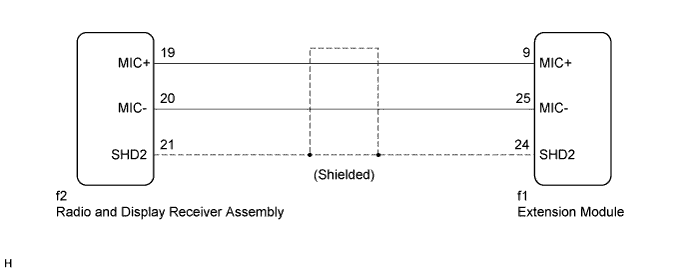
INSPECTION PROCEDURE
| 1.CHECK HARNESS AND CONNECTOR (RADIO AND DISPLAY RECEIVER ASSEMBLY - EXTENSION MODULE) |
Disconnect the radio and display receiver assembly connector.
Disconnect the extension module connector.
Measure the resistance according to the value(s) in the table below.
- Standard Resistance:
Tester Connection Condition Specified Condition f2-19 (MIC+) - f1-9 (MIC+) Always Below 1 Ω f2-20 (MIC-) - f1-25 (MIC-) Always Below 1 Ω f2-21 (SHD2) - f1-24 (SHD2) Always Below 1 Ω f2-19 (MIC+) - Body ground Always 10 kΩ or higher f2-20 (MIC-) - Body ground Always 10 kΩ or higher f2-21 (SHD2) - Body ground Always 10 kΩ or higher
|
| ||||
| OK | ||
| ||