Camshaft -- Installation |
| 1. INSTALL CAMSHAFT TIMING GEAR ASSEMBLY |
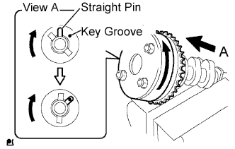
Put the camshaft timing gear and camshaft together with the straight pin and key groove misaligned, as shown in the illustration.
 |
Turn the camshaft timing gear as shown in the illustration while pushing it gently against the camshaft. Push further at the position where the pin fits into the groove.
- NOTICE:
- Be sure not to turn the camshaft timing gear to the retard direction (clockwise).
 |
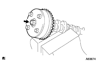
Check that there is no clearance between the timing gear and camshaft flange.
 |
Tighten the flange bolt with the camshaft timing gear assembly fixed in place.
- Torque:
- 54 N*m{551 kgf*cm, 40 ft.*lbf}
 |
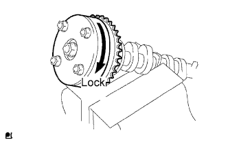
Check that the camshaft timing gear assembly can move to the retard direction (clockwise) and is locked in the most retarded position.
 |
| 2. INSTALL CAMSHAFT |
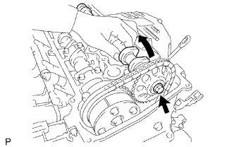
Apply a light coat of engine oil to the journal portion of the camshaft.
Install the timing chain onto the camshaft timing gear with the paint mark aligned with the timing mark on the camshaft timing gear as shown in the illustration.
 |
Examine the front marks and numbers, and check that the order is as shown in the illustration. Then install the bearing caps into the cylinder head.
 |
Apply a light coat of engine oil on the threads and under the heads of the bearing cap bolts.
Using several steps, uniformly tighten the 10 bearing cap bolts in the sequence shown in the illustration.
- Torque:
- No. 1 bearing:
- 30 N*m{301 kgf*cm, 22 ft.*lbf}
- No. 3 bearing:
- 9.0 N*m{92 kgf*cm, 80 in.*lbf}
 |
| 3. INSTALL NO. 2 CAMSHAFT |
Apply a light coat of engine oil to the journal portion of the No. 2 camshaft.
 |
Put the No. 2 camshaft on the cylinder head with the paint mark on the chain aligned with the timing mark on the camshaft timing sprocket.
While holding the No. 2 camshaft by hand, temporarily tighten the camshaft timing sprocket set bolt.
 |
Examine the front marks and numbers, and check that the order is as shown in the illustration. Then install the bearing caps onto the cylinder head.
 |
Apply a light coat of engine oil to the threads and under the heads of the bearing cap bolts.
Using several steps, uniformly tighten the 10 bearing cap bolts in the sequence shown in the illustration.
- Torque:
- No. 2 bearing:
- 30 N*m{301 kgf*cm, 22 ft.*lbf}
- No. 3 bearing:
- 9.0 N*m{92 kgf*cm, 80 in.*lbf}
 |
While holding the camshaft with a wrench, tighten the camshaft timing sprocket set bolt.
- Torque:
- 54 N*m{551 kgf*cm, 40 ft.*lbf}
- NOTICE:
- Be careful not to damage the valve lifter.
 |
Check that the paint marks on the chain are aligned with the timing marks on the camshaft timing gear and camshaft timing sprocket. Also, check that the crankshaft pulley groove is aligned with the timing mark "0" on the timing mark chain cover.
 |
| 4. INSTALL NO. 1 CHAIN TENSIONER ASSEMBLY |
Release the ratchet pawl, then fully push in the plunger and set the hook to the pin so that the plunger is in the position shown in the illustration.
 |
Install a new gasket and the chain tensioner with the 2 nuts.
- Torque:
- 9.0 N*m{92 kgf*cm, 80 in.*lbf}
- NOTICE:
- When installing the chain tensioner, set the hook again if the hook releases the plunger.
 |
Turn the crankshaft counterclockwise, then disconnect the hook from the pin.
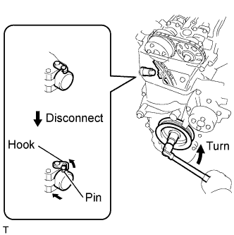 |
Turn the crankshaft clockwise, then check that the plunger is extended.
 |
| 5. SET NO. 1 CYLINDER TO TDC/COMPRESSION |
Turn the crankshaft pulley until the groove and the timing mark "0" on the timing chain cover are aligned.
 |
Check that each timing mark on the camshaft timing gear and sprocket is aligned with each timing mark located on the No. 1 and No. 2 bearing caps as shown in the illustration.
If not, turn the crankshaft pulley 1 revolution (360°) to align the timing marks as illustrated.
Place paint marks on the chain in alignment with the timing marks on the camshaft timing gear and camshaft timing sprocket.
| 6. CHECK VALVE CLEARANCE |
Check only the valves indicated in the illustration.
Using a feeler gauge, measure the clearance between the valve lifter and camshaft.
- Standard Valve Clearance (Cold):
Item Specified Condition Intake 0.19 to 0.29 mm (0.00748 to 0.0114 in.) Exhaust 0.38 to 0.48 mm (0.0150 to 0.0189 in.)
Record any out-of-specification valve clearance measurements. They will be used later to determine the required replacement valve clearance lifters.
 |
Turn the crankshaft 1 revolution (360°) and set the No. 4 cylinder to TDC/compression.
Check only the valves indicated in the illustration.
Using a feeler gauge, measure the clearance between the valve lifter and camshaft.
- Standard Valve Clearance (Cold):
Item Specified Condition Intake 0.19 to 0.29 mm (0.00748 to 0.0114 in.) Exhaust 0.38 to 0.48 mm (0.0150 to 0.0189 in.)
Record any out-of-specification valve clearance measurements. They will be used later to determine the required replacement valve lifters.
 |
| 7. ADJUST VALVE CLEARANCE |
Set No. 1 cylinder to TDC/compression (COROLLA_ZRE142 RM0000032Z3011X_01_0006.html).
Remove the No. 1 chain tensioner (COROLLA_ZRE142 RM0000032Z3011X_01_0013.html).
Loosen the camshaft timing sprocket (COROLLA_ZRE142 RM0000032Z3011X_01_0007.html).
Remove the No. 2 camshaft (COROLLA_ZRE142 RM0000032Z3011X_01_0008.html).
Remove the camshaft (COROLLA_ZRE142 RM0000032Z3011X_01_0009.html).
Remove the valve lifters.
Using a micrometer, measure the thickness of the removed valve lifters.
 |
Calculate the thickness of a new lifter so that the valve clearance comes within the specified values.
- New Lifter Thickness:
Item Specification Intake A = B + (C - 0.24 mm (0.00945 in.)) Exhaust A = B + (C - 0.43 mm (0.0169 in.))
CALCULATION EXAMPLE (Intake):A New lifter thickness B Used lifter thickness C Measured valve clearance - Measured intake valve clearance = 0.40 mm (0.0157 in.)
(Measured - Specification = Excess clearance) - 0.40 mm (0.0157 in.) - 0.24 mm (0.00945 in.) = 0.16 mm (0.00630 in.)
- Measured used lifter thickness = 5.250 mm (0.2067 in.)
- New lifter thickness = 5.410 mm (0.2130 in.)
(Excess clearance + Used lifter thickness = Ideal new lifter) - 0.16 mm (0.00630 in.) + 5.250 mm (0.2067 in.) = 5.410 mm (0.2130 in.)
- Closest new lifter = 5.420 mm (0.2134 in.)
- Select No. 42 lifter
Select a new lifter with a thickness as close as possible to the calculated values.
- HINT:
- Lifters are available in 35 sizes in increments of 0.020 mm (0.000787 in.), from 5.060 to 5.740 mm (0.1992 to 0.2260 in.).
The identification number inside the valve lifters shows the value to 2 decimal places. (The illustration shows 5.420 mm (0.2134 in.)
Valve lifter selection chart (intake).

New Lifter Thickness Lifter No. Thickness
mm (in.)Lifter No. Thickness
mm (in.)Lifter No. Thickness
mm (in.)06 5.060 (0.1992) 30 5.300 (0.2087) 54 5.540 (0.2181) 08 5.080 (0.2000) 32 5.320 (0.2094) 56 5.560 (0.2189) 10 5.100 (0.2008) 34 5.340 (0.2102) 58 5.580 (0.2197) 12 5.120 (0.2016) 36 5.360 (0.2110) 60 5.600 (0.2205) 14 5.140 (0.2024) 38 5.380 (0.2118) 62 5.620 (0.2213) 16 5.160 (0.2031) 40 5.400 (0.2126) 64 5.640 (0.2220) 18 5.180 (0.2039) 42 5.420 (0.2134) 66 5.660 (0.2228) 20 5.200 (0.2047) 44 5.440 (0.2142) 68 5.680 (0.2236) 22 5.220 (0.2055) 46 5.460 (0.2150) 70 5.700 (0.2244) 24 5.240 (0.2063) 48 5.480 (0.2157) 72 5.720 (0.2252) 26 5.260 (0.2071) 50 5.500 (0.2165) 74 5.740 (0.2260) 28 5.280 (0.2079) 52 5.520 (0.2173) - - - Standard intake valve clearance (cold):
- 0.19 to 0.29 mm (0.00748 to 0.0114 in.)
The 5.250 mm (0.2067 in.) lifter is installed, and the measured clearance is 0.400 mm (0.0157 in.). Replace the 5.250 mm (0.2067 in.) lifter with a new No. 42 lifter.
Valve lifter selection chart (exhaust).

New Lifter Thickness Lifter No. Thickness
mm (in.)Lifter No. Thickness
mm (in.)Lifter No. Thickness
mm (in.)06 5.060 (0.1992) 30 5.300 (0.2087) 54 5.540 (0.2181) 08 5.080 (0.2000) 32 5.320 (0.2094) 56 5.560 (0.2189) 10 5.100 (0.2008) 34 5.340 (0.2102) 58 5.580 (0.2197) 12 5.120 (0.2016) 36 5.360 (0.2110) 60 5.600 (0.2205) 14 5.140 (0.2024) 38 5.380 (0.2118) 62 5.620 (0.2213) 16 5.160 (0.2031) 40 5.400 (0.2126) 64 5.640 (0.2220) 18 5.180 (0.2039) 42 5.420 (0.2134) 66 5.660 (0.2228) 20 5.200 (0.2047) 44 5.440 (0.2142) 68 5.680 (0.2236) 22 5.220 (0.2055) 46 5.460 (0.2150) 70 5.700 (0.2244) 24 5.240 (0.2063) 48 5.480 (0.2157) 72 5.720 (0.2252) 26 5.260 (0.2071) 50 5.500 (0.2165) 74 5.740 (0.2260) 28 5.280 (0.2079) 52 5.520 (0.2173) - - - Standard exhaust valve clearance (cold):
- 0.38 to 0.48 mm (0.0150 to 0.0189 in.)
The 5.340 mm (0.2102 in.) lifter is installed, and the measured clearance is 0.510 mm (0.0201 in.). Replace the 5.340 mm (0.2102 in.) lifter with a new No. 42 lifter.
Install the selected valve lifter.
Install the camshaft (COROLLA_ZRE142 RM0000032Z4011X_01_0001.html).
Install the No. 2 camshaft (COROLLA_ZRE142 RM0000032Z4011X_01_0002.html).
Install the No. 1 chain tensioner (COROLLA_ZRE142 RM0000032Z4011X_01_0012.html).
| 8. INSTALL CYLINDER HEAD COVER SUB-ASSEMBLY |
Remove any old packing material from the contact surface.
Apply seal packing to the 2 locations shown in the illustration.
- Seal packing:
- Toyota Genuine Seal Packing Black, Three Bond 1207B or equivalent
- NOTICE:
- Remove any oil from the contact surface.
- Install the oil pan within 3 minutes of applying seal packing.
- Do not add engine oil for at least 2 hours after installing the oil pan.
 |
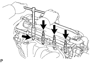
Install the cylinder head cover gasket and sub-assembly with the 8 bolts and 2 nuts.
- Torque:
- Bolt A:
- 11 N*m{112 kgf*cm, 8 ft.*lbf}
- Bolt B:
- 14 N*m{143 kgf*cm, 10 ft.*lbf}
- Nut:
- 11 N*m{112 kgf*cm, 8 ft.*lbf}
 |
Install the 2 engine wire harness brackets with the 2 bolts.
- Torque:
- 8.4 N*m{86 kgf*cm, 74 in.*lbf}
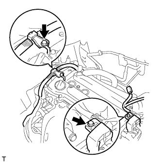 |
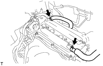
Connect the 2 ventilation hoses to the cylinder head cover.
 |
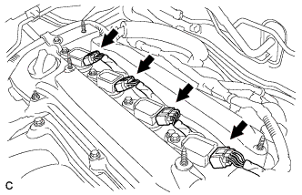
| 9. INSTALL SPARK PLUG |
Install the 4 spark plugs.
- Torque:
- 19 N*m{194 kgf*cm, 14 ft.*lbf}
 |
| 10. INSTALL IGNITION COIL ASSEMBLY |
Install the 4 ignition coils with the 4 bolts.
- Torque:
- 9.0 N*m{92 kgf*cm, 80 in.*lbf}
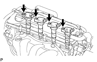 |
Connect the 4 ignition coil connectors.
 |
| 11. INSPECT FOR OIL LEAK |
| 12. INSPECT IGNITION TIMING |
- NOTICE:
- Turn all the electrical systems and the A/C off.
- When checking the ignition timing, move the shift lever to neutral.
Warm up and stop the engine.
When using the Techstream:
Connect the Techstream to the DLC3.
Turn the ignition switch to ON.
Turn the Techstream on.
Enter the following menus: Power Train / Engine and ECT / Data List / IGN Advance
Start the engine.
According to the display on the Techstream, read the Data List.
- Standard ignition timing:
- 5 to 15° BTDC at idle
Check that the ignition timing advances immediately when the engine speed is increased.
Turn the ignition switch off.
Disconnect the Techstream from the DLC3.
When not using the Techstream:
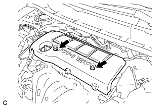
Remove the No. 1 engine cover sub-assembly (COROLLA_ZRE142 RM000001BC301CX_01_0101.html).
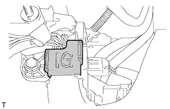
Open the ignition cover located to the right of the No. 4 ignition coil.
Pull the wire harness out from the IG cover.
Connect the timing light to the wire harness.
- NOTICE:
- Use a timing light that detects the primary signal.
Using SST, connect terminals 13 (TC) and 4 (CG) of the DLC3.
- SST
- 09843-18040
Allow the engine to idle and check the ignition timing.
- Standard ignition timing:
- 8 to 12° BTDC at idle
- HINT:
- Run the engine at 1000 to 1300 rpm for 5 seconds, then check that the engine speed returns to idle speed.
Disconnect SST from terminals 13 (TC) and 4 (CG) of the DLC3.
Allow the engine to idle and check the ignition timing.
- Standard ignition timing:
- 5 to 15° BTDC at idle
Check that the ignition timing advances immediately when the engine speed is increased.
Turn the ignition switch off.
Remove the timing light.
Close the IG cover.
Install the No. 1 engine cover sub-assembly (COROLLA_ZRE142 RM000001BC101CX_01_0268.html).

| 13. INSTALL NO. 1 ENGINE COVER SUB-ASSEMBLY |
Install the No. 1 engine cover sub-assembly with the 2 nuts.
 |
| 14. INSTALL ENGINE UNDER COVER RH |