Room Temperature Sensor Removal
DISCONNECT CABLE FROM NEGATIVE BATTERY TERMINAL
REMOVE LOWER INSTRUMENT PANEL FINISH PANEL SUB-ASSEMBLY
REMOVE STEERING WHEEL ASSEMBLY
REMOVE LOWER STEERING COLUMN COVER
REMOVE UPPER STEERING COLUMN COVER
REMOVE LOWER INSTRUMENT PANEL FINISH PANEL LH
REMOVE INSTRUMENT PANEL FINISH PANEL END LH
REMOVE INSTRUMENT CLUSTER FINISH PANEL ASSEMBLY
REMOVE NO. 1 SWITCH HOLE BASE (w/o Smart Key System)
REMOVE NO. 1 SWITCH HOLE BASE (w/ Smart Key System)
REMOVE ROOM TEMPERATURE SENSOR
Room Temperature Sensor -- Removal |
| 1. DISCONNECT CABLE FROM NEGATIVE BATTERY TERMINAL |
- CAUTION:
- Wait at least 90 seconds after disconnecting the cable from the negative (-) battery terminal to disable the SRS system (COROLLA_ZRE142 RM000000KT10H0X.html).
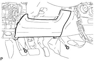
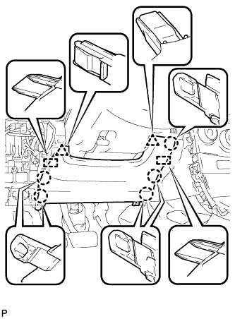
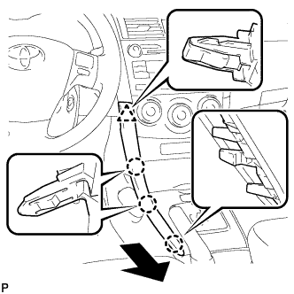
| 2. REMOVE LOWER INSTRUMENT PANEL FINISH PANEL SUB-ASSEMBLY |
Remove the 2 screws <B>.
Disengage the 5 claws, 2 guides and 2 clips, and then remove the lower instrument panel finish panel sub-assembly.
| 3. REMOVE STEERING WHEEL ASSEMBLY |
(COROLLA_ZRE142 RM0000035Q401KX.html)
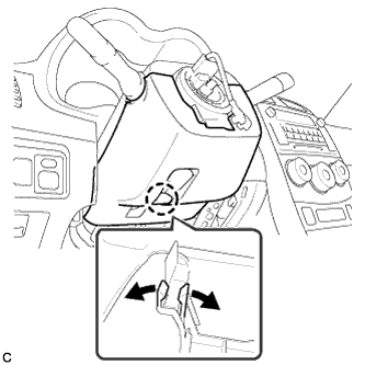
| 4. REMOVE LOWER STEERING COLUMN COVER |
- NOTICE:
- Removing the lower steering column cover in the incorrect order will cause the lower steering column cover to break.
Push the right and left sides of the lower steering column cover, and disengage the 4 claws.
Insert your fingers into the opening of the tilt lever of the lower steering column cover to disengage the claw.
- HINT:
- Spread the claw to disengage it.
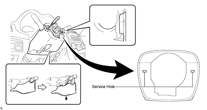
Using a screwdriver, insert the tip into each service hole to disengage the 2 claws and remove the lower steering column cover as shown in the illustration.
| 5. REMOVE UPPER STEERING COLUMN COVER |
Disengage the claw and the 2 pins, and remove the upper steering column cover.
| 6. REMOVE LOWER INSTRUMENT PANEL FINISH PANEL LH |
Disengage the 3 claws and clip, and then remove the lower instrument panel finish panel LH.
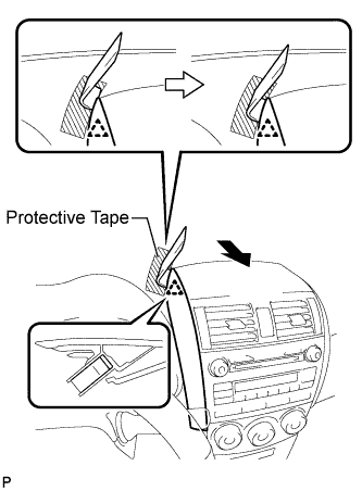
| 7. REMOVE INSTRUMENT PANEL FINISH PANEL END LH |
Apply protective tape to the area shown in the illustration.
Insert a roof moulding remover and slide it toward the clip.
Pull the remover with both hands to disengage the clip as shown in the illustration.
Disengage the 2 claws and clip, and remove the instrument panel finish panel end LH.
| 8. REMOVE INSTRUMENT CLUSTER FINISH PANEL ASSEMBLY |
Operate the tilt lever to lower the steering wheel assembly.
Apply protective tape to the area shown in the illustration.
Disengage the guide, claw and 3 clips, and then remove the instrument cluster finish panel assembly.
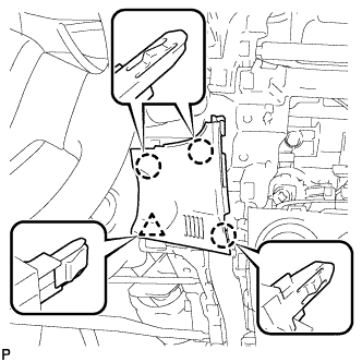
| 9. REMOVE NO. 1 SWITCH HOLE BASE (w/o Smart Key System) |
Disengage the 3 claws and clip, and then remove the No. 1 switch hole base.
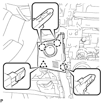
| 10. REMOVE NO. 1 SWITCH HOLE BASE (w/ Smart Key System) |
Disengage the 3 claws and clip.
Disconnect the connector and remove the No. 1 switch hole base.
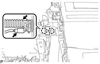
| 11. REMOVE ROOM TEMPERATURE SENSOR |
Disconnect the connector.
Disengage the air hose.
Disengage the 2 claws and remove the room temperature sensor.