Parking Brake Cable (For Rear Drum Brake) Installation
Brake. Corolla. Zre142 Aze141
INSTALL NO. 3 PARKING BRAKE CABLE CLAMP
INSTALL NO. 3 PARKING BRAKE CABLE ASSEMBLY
INSTALL REAR BRAKE SHOE (for Rear Side)
INSTALL REAR BRAKE STRUT SET
INSTALL REAR BRAKE SHOE (for Front Side)
INSPECT REAR DRUM BRAKE
INSTALL REAR BRAKE DRUM
INSTALL FRONT NO. 2 FLOOR HEAT INSULATOR
INSTALL FRONT NO. 1 FLOOR HEAT INSULATOR
INSTALL FRONT EXHAUST PIPE ASSEMBLY
INSTALL NO. 1 PARKING BRAKE CABLE ASSEMBLY
INSTALL PARKING BRAKE CABLE END STOPPER
INSTALL PARKING BRAKE EQUALIZER
INSTALL PARKING BRAKE LEVER ASSEMBLY
CONNECT PARKING BRAKE EQUALIZER
INSTALL NO. 3 BELT ANCHOR REINFORCEMENT SUB-ASSEMBLY
INSTALL NO. 2 BELT ANCHOR REINFORCEMENT SUB-ASSEMBLY
ADJUST REAR DRUM BRAKE SHOE CLEARANCE
ADJUST PARKING BRAKE TRAVEL
INSTALL CONSOLE BOX ASSEMBLY
INSTALL FRONT SEAT ASSEMBLY LH (for Manual Seat)
INSTALL FRONT SEAT ASSEMBLY LH (for Power Seat)
INSTALL FRONT SEAT ASSEMBLY RH
CONNECT CABLE TO NEGATIVE BATTERY TERMINAL (w/ Front Seat Side Airbag)
INSPECT SRS WARNING LIGHT (w/ Front Seat Side Airbag)
INSPECT FOR EXHAUST GAS LEAK
INSTALL REAR WHEELS
Parking Brake Cable (For Rear Drum Brake) -- Installation |
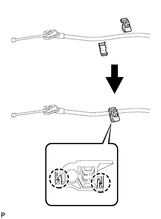
| 1. INSTALL NO. 3 PARKING BRAKE CABLE CLAMP |
Engage the 2 claws together to install a new No. 3 parking brake cable clamp to the No. 3 parking brake cable assembly.
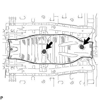
| 2. INSTALL NO. 3 PARKING BRAKE CABLE ASSEMBLY |
Install the No. 3 parking brake cable assembly with the 2 bolts.
- Torque:
- 6.0 N*m{61 kgf*cm, 53 in.*lbf}
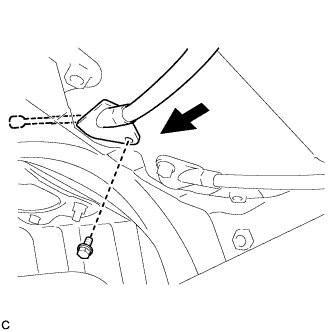
Insert the No. 3 parking brake cable assembly into the body.
Install the bolt.
- Torque:
- 6.0 N*m{61 kgf*cm, 53 in.*lbf}
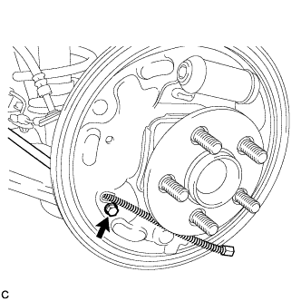
Install the No. 3 parking brake cable assembly to the backing plate with the bolt.
- Torque:
- 8.0 N*m{82 kgf*cm, 71 in.*lbf}
Install the bolt.
- Torque:
- 6.0 N*m{61 kgf*cm, 53 in.*lbf}
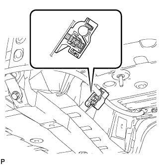
Engage the clamp to the No. 3 parking brake cable assembly.
Install the No. 3 parking brake cable clamp.
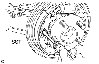
| 3. INSTALL REAR BRAKE SHOE (for Rear Side) |
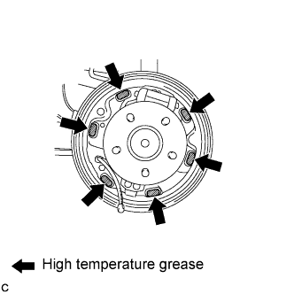
Apply high temperature grease to the surface of the backing plate that contacts the shoes as shown in the illustration.
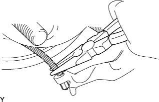
Using needle-nose pliers, install the parking brake cable to the rear brake parking brake shoe lever sub-assembly.
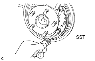
Using SST, install the rear brake shoe, pin, shoe hold down spring and shoe hold down spring cup.
- SST
- 09718-00011
| 4. INSTALL REAR BRAKE STRUT SET |
Apply high temperature grease to the adjustment bolt.
Install the rear brake strut set to the rear brake shoe.
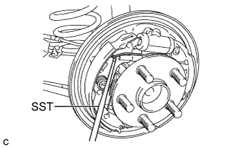
| 5. INSTALL REAR BRAKE SHOE (for Front Side) |
Using SST, install the rear brake shoe, pin, shoe hold down spring and shoe hold down spring cup.
- SST
- 09718-00011
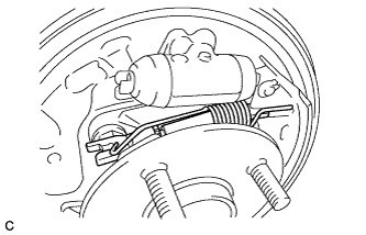
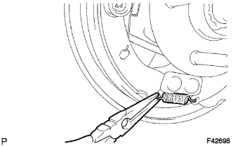
Using needle-nose pliers, install the tension spring to the rear brake shoe.
Using SST, install the shoe return spring to the rear brake shoe.
- SST
- 09921-00010
- NOTICE:
- Do not damage the wheel cylinder boot.
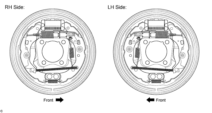
| 6. INSPECT REAR DRUM BRAKE |
Inspect that each part is installed properly as shown in the illustration.
- NOTICE:
- There should be no oil or grease adhering to the friction surfaces of the shoe lining or the drum.
Measure the brake drum inner diameter and the diameter of the brake shoes. Check that the difference between the diameters is equal to the specified shoe clearance.
- Shoe clearance:
- 0.6 mm (0.0236 in.)
| 7. INSTALL REAR BRAKE DRUM |
Install the rear brake drum.
| 8. INSTALL FRONT NO. 2 FLOOR HEAT INSULATOR |
Install the front No. 2 floor heat insulator with the 2 nuts.
- Torque:
- 5.5 N*m{56 kgf*cm, 49 in.*lbf}
| 9. INSTALL FRONT NO. 1 FLOOR HEAT INSULATOR |
Install the front No. 1 floor heat insulator with the 3 nuts.
- Torque:
- 5.5 N*m{56 kgf*cm, 49 in.*lbf}
| 10. INSTALL FRONT EXHAUST PIPE ASSEMBLY |
Using a vernier caliper, measure the free length of the compression springs.
Minimum (front)
| 41.5 mm (1.64 in.)
|
Minimum (rear)
| 38.5 mm (1.52 in.)
|
- HINT:
- If the free length is less than the minimum, replace the compression spring.
Fully insert 2 new gaskets to the exhaust manifold and front exhaust pipe assembly.
Using a plastic hammer and wooden block, tap in each gasket until its surface is flush with the exhaust manifold and front exhaust pipe assembly.
Text in Illustration*1
| Exhaust Manifold and Front Exhaust Pipe Assembly
|
*2
| Gasket
|
*3
| Wooden Block
|
- NOTICE:
- Be careful with the installation direction of the gaskets.
- Do not reuse the gaskets.
- Do not damage the gaskets.
- Do not push in the gaskets by using the exhaust pipe when connecting it.
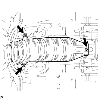
Connect the front exhaust pipe assembly to the 2 exhaust pipe supports.
Install the front exhaust pipe assembly with the 4 bolts and 4 compression springs.
- Torque:
- 43 N*m{440 kgf*cm, 32 ft.*lbf}
Connect the heated oxygen sensor connector.
| 11. INSTALL NO. 1 PARKING BRAKE CABLE ASSEMBLY |
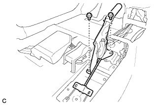
Pass the No. 1 parking brake cable assembly through the parking brake lever sub-assembly.
Bend the parking brake lever claw.
Temporarily install the adjusting nut and the lock nut to the No. 1 parking brake cable assembly.
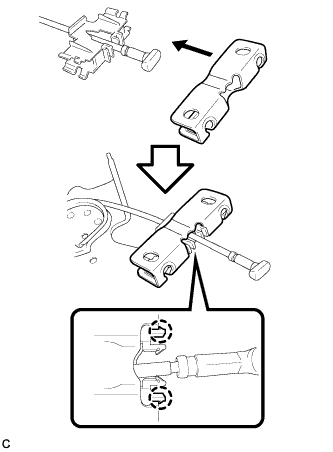
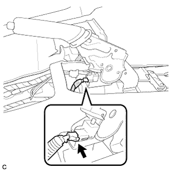
| 12. INSTALL PARKING BRAKE CABLE END STOPPER |
Install the parking brake cable end stopper to the No. 1 parking brake cable assembly.
| 13. INSTALL PARKING BRAKE EQUALIZER |
Engage the 2 claws to install the parking brake equalizer to the parking brake cable end stopper.
Engage the 2 claws to install the parking brake cable end stopper to the No. 1 parking brake cable assembly.
| 14. INSTALL PARKING BRAKE LEVER ASSEMBLY |
Install the parking brake lever assembly with the 2 bolts.
- Torque:
- 15 N*m{148 kgf*cm, 11 ft.*lbf}
Connect the parking brake switch connector.
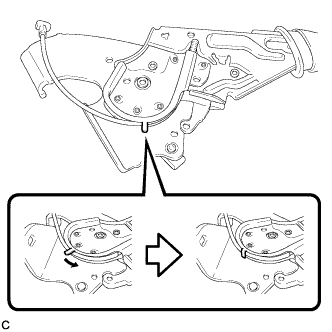
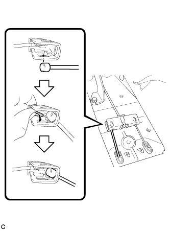
| 15. CONNECT PARKING BRAKE EQUALIZER |
Connect the parking brake equalizer to the No. 3 parking brake cable assembly as shown in the illustration.
Connect the parking brake equalizer to the No. 2 parking brake cable assembly.
- HINT:
- Perform the same procedure for the No. 3 parking brake cable assembly.
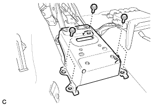
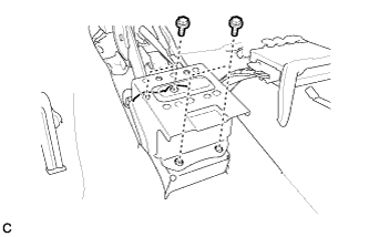
| 16. INSTALL NO. 3 BELT ANCHOR REINFORCEMENT SUB-ASSEMBLY |
Install the No. 3 belt anchor reinforcement sub-assembly with the 5 bolts.
- Torque:
- 27 N*m{275 kgf*cm, 19 ft.*lbf}
Install the floor carpet.
| 17. INSTALL NO. 2 BELT ANCHOR REINFORCEMENT SUB-ASSEMBLY |
Install the No. 2 belt anchor reinforcement sub-assembly with the 4 bolts.
- Torque:
- 27 N*m{275 kgf*cm, 19 ft.*lbf}
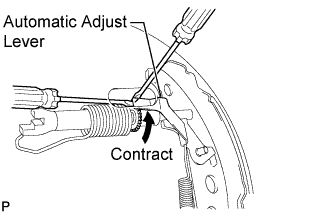
| 18. ADJUST REAR DRUM BRAKE SHOE CLEARANCE |
Temporarily install the 2 wheel nuts.
Remove the shoe adjusting hole plug, and turn the adjuster to expand the shoe until the drum locks.
Hold the automatic adjust lever away from the adjuster, and contract the brake shoe by turning the adjust bolt using another screwdriver until the drum can rotate smoothly.
- Standard:
- 11 notches
Install the hole plug.
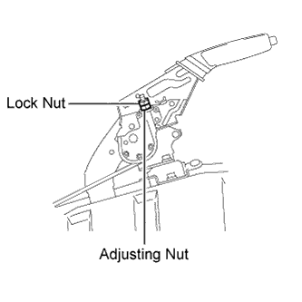
| 19. ADJUST PARKING BRAKE TRAVEL |
Remove the upper console box assembly (COROLLA_ZRE142 RM000002XV501QX.html).
Completely release the parking brake lever.
Loosen the lock nut and the adjusting nut to completely release the parking brake cable.
Fully depress the brake lever 3 to 5 times with the engine stopped.
Turn the adjusting nut until the parking brake lever travel is corrected to within the specified range.
- Parking brake lever travel:
- 6 to 9 notches at 200 N (20 kgf, 45.0 lbf)
Using a wrench or an equivalent tool, hold the adjusting nut and tighten the lock nut.
- Torque:
- 6.0 N*m{61 kgf*cm, 53 in.*lbf}
Operate the parking brake lever 3 to 4 times, and check the parking brake lever travel.
Check whether the parking brake drags or not.
Install the upper console box assembly (COROLLA_ZRE142 RM000002XV301QX.html).
| 20. INSTALL CONSOLE BOX ASSEMBLY |
- HINT:
- Refer to the instructions for Installation of the front console box (Link).
| 21. INSTALL FRONT SEAT ASSEMBLY LH (for Manual Seat) |
- HINT:
- Refer to the instructions for Installation of the front seat assembly (COROLLA_ZRE142 RM000000Z8T0D2X.html).
| 22. INSTALL FRONT SEAT ASSEMBLY LH (for Power Seat) |
- HINT:
- Refer to the instructions for Installation of the front seat assembly (COROLLA_ZRE142 RM000000Z8T0D1X.html).
| 23. INSTALL FRONT SEAT ASSEMBLY RH |
- HINT:
- Perform the same procedure for the LH side.
| 24. CONNECT CABLE TO NEGATIVE BATTERY TERMINAL (w/ Front Seat Side Airbag) |
| 25. INSPECT SRS WARNING LIGHT (w/ Front Seat Side Airbag) |
- HINT:
- COROLLA_ZRE142 RM000000XFD0GSX.html.
| 26. INSPECT FOR EXHAUST GAS LEAK |
- Torque:
- 103 N*m{1050 kgf*cm, 76 ft.*lbf}