Engine Unit -- Installation |
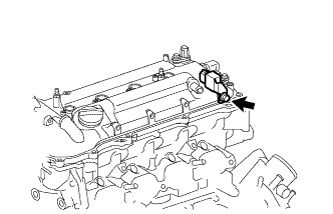
| 1. INSTALL RADIO SETTING CONDENSER |
Install the radio setting condenser with the bolt.
- Torque:
- 10 N*m{102 kgf*cm, 7 ft.*lbf}
 |
| 2. INSTALL THERMOSTAT |
Install a new gasket on the thermostat.
Install the thermostat to the water inlet with the jiggle valve upward.
- HINT:
- The jiggle valve may be set to within 10° on either side of the indicated position.
 |
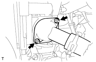
| 3. INSTALL WATER INLET |
Install the water inlet with the 2 nuts.
- Torque:
- 10 N*m{102 kgf*cm, 7 ft.*lbf}
 |
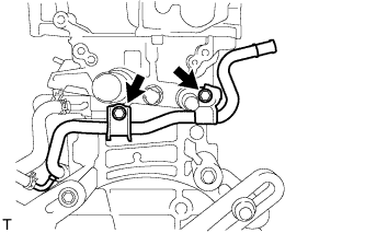
| 4. INSTALL INLET WATER HOSE |
Install the inlet water hose with the 2 clamps.
 |
| 5. INSTALL WATER BY-PASS HOSE |
Install the water by-pass hose with the clamp.
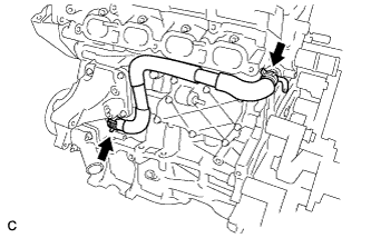
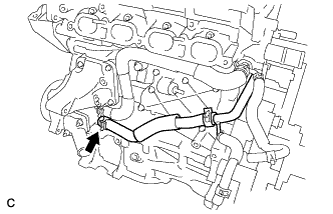
| 6. INSTALL NO. 1 WATER BY-PASS PIPE |
Install the No. 1 water by-pass pipe with the 2 bolts.
- Torque:
- 21 N*m{214 kgf*cm, 16 ft.*lbf}
 |
| 7. CONNECT NO. 3 WATER BY-PASS HOSE |
Connect the No. 3 water by-pass hose to the inlet water housing.
 |
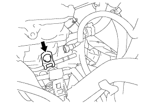
| 8. INSTALL VENTILATION HOSE |
Install the ventilation hose.
| 9. INSTALL EXHAUST MANIFOLD |
Install a new gasket onto the exhaust manifold.
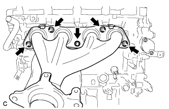 |
Install the exhaust manifold with the 5 nuts.
- Torque:
- 37 N*m{377 kgf*cm, 27 ft.*lbf}
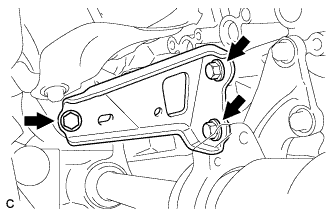
| 10. INSTALL MANIFOLD STAY |
Install the manifold stay with the 3 bolts.
- Torque:
- 43 N*m{439 kgf*cm, 32 ft.*lbf}
 |
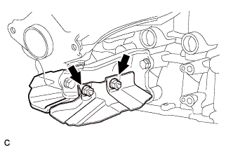
Install the 2 drive shaft heat insulator sub-assemblies with the 2 nuts.
- Torque:
- 18 N*m{184 kgf*cm, 13 ft.*lbf}
 |
| 11. INSTALL NO. 1 EXHAUST MANIFOLD HEAT INSULATOR |
Install the No. 1 exhaust manifold heat insulator with the 4 bolts.
- Torque:
- 12 N*m{122 kgf*cm, 9 ft.*lbf}
 |
| 12. INSTALL OIL LEVEL DIPSTICK SUB-ASSEMBLY |
Apply engine oil to a new O-ring.
 |
Install the oil level dipstick with the bolt through the new O-ring.
- Torque:
- 21 N*m{214 kgf*cm, 16 ft.*lbf}
| 13. INSTALL IGNITION COIL ASSEMBLY |
Install the 4 ignition coils with the 4 bolts.
- Torque:
- 10 N*m{102 kgf*cm, 7 ft.*lbf}
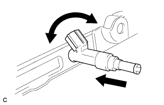
| 14. INSTALL FUEL INJECTOR ASSEMBLY |
Install 4 new injector vibration insulators to the 4 fuel injector assemblies.
 |
Install 4 new injector vibration insulators to the 4 fuel injector assemblies.
Apply a light coat of gasoline or spindle oil to the contact surfaces of the the O-rings of the fuel injector assemblies.
While turning the fuel injector assembly left and right, install it onto the fuel delivery pipe sub-assembly.
- NOTICE:
- Do not twist the O-ring.
- After installing the fuel injectors, check that they turn smoothly.
 |
| 15. INSTALL NO. 1 DELIVERY PIPE SPACER |
Install the 2 No. 1 delivery pipe spacers onto the cylinder head.
Text in Illustration *a Delivery Pipe Side *b Cylinder Head Side - NOTICE:
- Install the No. 1 delivery pipe spacers in the correct direction.
 |
| 16. INSTALL FUEL DELIVERY PIPE SUB-ASSEMBLY |
Install the fuel delivery pipe sub-assembly with the 4 fuel injector assemblies, then temporarily install the 2 bolts.
- NOTICE:
- Do not drop the fuel injectors when installing the fuel delivery pipe sub-assembly.
- Check that the fuel injector assemblies rotate smoothly after installing the fuel delivery pipe sub-assembly.
 |
Tighten the 2 bolts to the specified torque.
- Torque:
- 21 N*m{214 kgf*cm, 15 ft.*lbf}
|
Install the bolt to secure the fuel delivery pipe sub-assembly.
- Torque:
- 21 N*m{214 kgf*cm, 15 ft.*lbf}
 |
Install the wire harness bracket with the bolt.
- Torque:
- 5.0 N*m{51 kgf*cm, 44 in.*lbf}
 |
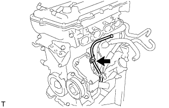
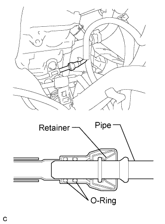
| 17. CONNECT FUEL TUBE SUB-ASSEMBLY |
Insert the fuel tube sub-assembly connector into the fuel delivery pipe until a "click" sound can be heard.
- NOTICE:
- Check that there are no scratches or foreign matter around the contact surfaces of the fuel tube connector and pipe before performing this work.
- After connecting the fuel tube, check that the fuel tube connector and pipe are securely connected by pulling on them.
 |
Install a new No. 2 fuel pipe clamp (Type B).
 |
Install a new No. 2 fuel pump clamp (Type A).
 |
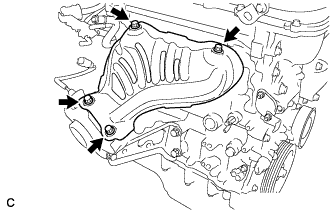
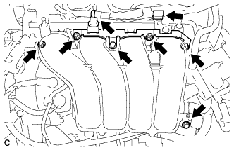
| 18. INSTALL INTAKE MANIFOLD |
Install a new gasket to the intake manifold.
Install the intake manifold and intake manifold stay with the 4 bolts and 2 nuts.
- Torque:
- 28 N*m{286 kgf*cm, 21 ft.*lbf}
 |
Connect the 2 water by-pass hoses.
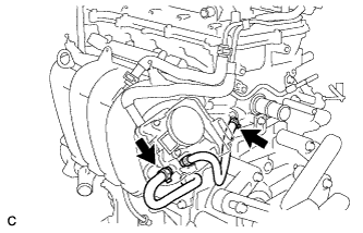 |
Connect the ventilation hose to the intake manifold.
Install the air tube with the 2 bolts.
- Torque:
- 10 N*m{102 kgf*cm, 7 ft.*lbf}
Install the wire harness bracket.
- Torque:
- 10 N*m{102 kgf*cm, 7 ft.*lbf}
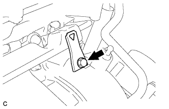
| 19. INSTALL FAN BELT ADJUSTING BAR |
Install the fan belt adjusting bar with the bolt.
- Torque:
- 19 N*m{194 kgf*cm, 14 ft.*lbf}
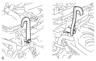
| 20. INSTALL ENGINE HANGER |
Remove the bolt and wire harness bracket.
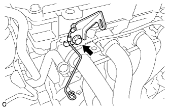 |
Install the 2 engine hangers with the 2 bolts.
- Torque:
- 43 N*m{439 kgf*cm, 32 ft.*lbf}
Part Name Part No. No. 1 engine hanger 12281-37021 No. 2 engine hanger 12282-37011 Bolt 91552-81050
 |
| 21. REMOVE ENGINE STAND |
Attach the engine to a sling device with the chain block.
Remove the engine from the engine stand.