Oil Pump -- Installation |
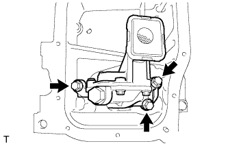
| 1. INSTALL OIL PUMP ASSEMBLY |
Install the oil pump with the 3 bolts.
- Torque:
- 21 N*m{214 kgf*cm, 16 ft.*lbf}
 |
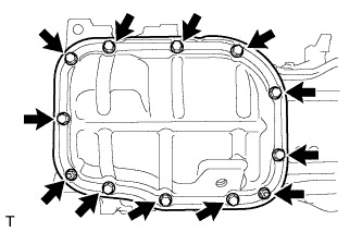
| 2. INSTALL NO. 2 OIL PAN SUB-ASSEMBLY |
Remove any old packing material and be careful not to drop any oil on the contact surfaces of the cylinder block and oil pan.
Apply a continuous bead of seal packing (Diameter 4.0 mm (0.157 in.)) as shown in the illustration.
- Seal packing:
- Toyota Genuine Seal Packing Black, Three Bond 1207B or equivalent
- NOTICE:
- Remove any oil from the contact surfaces.
- Install the oil pan within 3 minutes after applying seal packing.
- Do not start the engine for at least 2 hours after installing the oil pan.
 |
Install the No. 2 oil pan with the 10 bolts and 2 nuts.
- Torque:
- 10 N*m{102 kgf*cm, 7 ft.*lbf}
 |
| 3. INSTALL NO. 1 CRANKSHAFT POSITION SENSOR PLATE |
Install the sensor plate with the "F" mark facing forward.
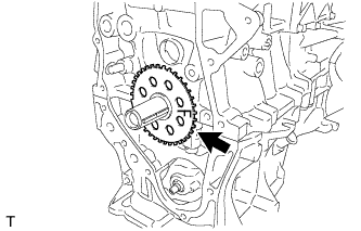 |
| 4. INSTALL NO. 2 CHAIN SUB-ASSEMBLY |
Set the crankshaft key as shown in the illustration.
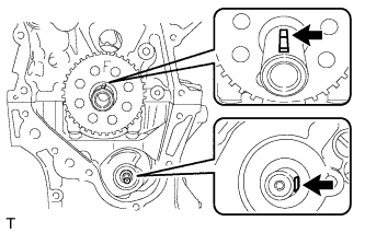 |
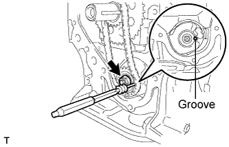
Turn the drive shaft so that the cutout faces the right horizontal position.
Align the yellow mark links with the timing marks of each gear as shown in the illustration.
 |
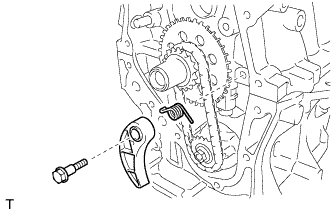
Install the sprockets onto the crankshaft and oil pump shaft with the chain on the gears.
Temporarily tighten the oil pump drive shaft sprocket with the nut.
Insert the damper spring into the adjusting hole, and then install the chain tensioner plate with the bolt.
- Torque:
- 10 N*m{102 kgf*cm, 7 ft.*lbf}
 |
Align the adjusting hole of the oil pump drive shaft sprocket with the groove of the oil pump.
 |
Insert a 3 mm diameter bar into the adjusting hole of the oil pump drive shaft gear to lock the gear in position, and then tighten the nut.
- Torque:
- 28 N*m{286 kgf*cm, 21 ft.*lbf}
 |
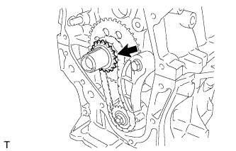
| 5. INSTALL CRANKSHAFT TIMING SPROCKET |
Install the crankshaft timing sprocket.
 |
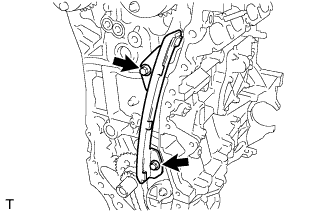
| 6. INSTALL NO. 1 CHAIN VIBRATION DAMPER |
Install the No. 1 chain vibration damper with the 2 bolts.
- Torque:
- 21 N*m{214 kgf*cm, 16 ft.*lbf}
 |
| 7. INSTALL NO. 2 CHAIN VIBRATION DAMPER |
Install the No. 2 chain vibration damper with the 2 bolts.
- Torque:
- 10 N*m{102 kgf*cm, 7 ft.*lbf}
 |
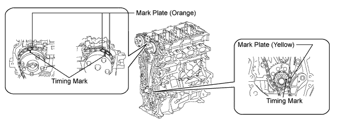
| 8. INSTALL CHAIN SUB-ASSEMBLY |
Check the No. 1 cylinder TDC/compression.
Temporarily tighten the crankshaft pulley bolt.
Turn the crankshaft counterclockwise to position the timing gear key to the top.
Remove the crankshaft pulley bolt.
Check the timing marks on each camshaft timing gear.


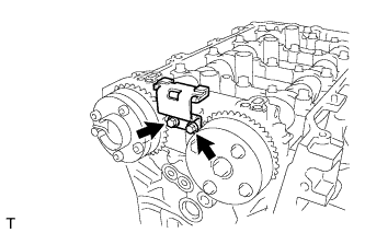
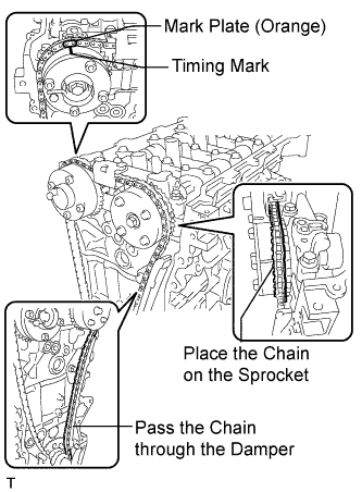
Align the mark plate (orange) with the timing mark of the No. 2 camshaft as shown in the illustration and install the chain.
- HINT:
- Be sure to position the mark plate at the front of the engine.
- The mark plate on the camshaft side is colored orange.
- Do not pass the chain around the sprocket of the camshaft timing gear assembly. Only place it on the sprocket.
- Pass the chain through the No. 1 vibration damper.
 |
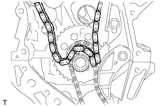
Place the chain on the crankshaft without passing it around the shaft.
 |
Hold the hexagonal portion of the camshaft with a wrench and turn the camshaft timing gear assembly counterclockwise to align the mark plate (orange) and timing mark.
- HINT:
- Be sure to position the mark plate at the front of the engine.
- The mark plate on the camshaft side is colored orange.
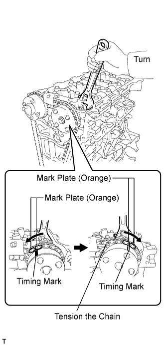 |
Hold the hexagonal portion of the camshaft with a wrench and turn the camshaft timing gear assembly clockwise.
- HINT:
- To tension the chain, slowly turn the camshaft timing gear assembly clockwise to prevent the chain from being misaligned.
Align the mark plate (yellow) and timing mark and install the chain to the crankshaft timing gear.
- HINT:
- The mark plate on the crankshaft side is colored yellow.
 |
Recheck each timing mark at TDC/compression.
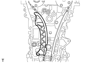
| 9. INSTALL CHAIN TENSIONER SLIPPER |
Install the chain tensioner slipper.
 |
| 10. INSTALL TIMING CHAIN COVER OIL SEAL |
Using SST and a hammer, tap in a new oil seal until its surface is flush with the timing chain cover sub-assembly edge.
- SST
- 09223-22010
- NOTICE:
- Keep the lip free from foreign matter.
- Do not tap the oil seal at an angle.
 |
Apply MP grease to the lip of the oil seal.
| 11. INSTALL TIMING CHAIN COVER SUB-ASSEMBLY |
Remove any old packing (FIPG) material and be careful not to drop any oil on the contact surfaces of the timing chain cover sub-assembly, cylinder head, and cylinder block.

Install 3 new O-rings.
 |
Apply seal packing as shown in the illustration.
- Seal packing:
- Toyota Genuine Seal Packing Black, Three Bond 1207B or equivalent
- Seal diameter:
- 5.0 mm (0.196 in.)
- NOTICE:
- Remove any oil from the contact surfaces.
- Install the chain cover within 3 minutes after applying seal packing.
- Do not start the engine for at least 2 hours after installing the timing chain cover sub-assembly.
Apply seal packing to the timing chain cover sub-assembly in a continuous line as shown in the following illustration.
- NOTICE:
- When the contact surfaces are wet, wipe them with oil-free cloth before applying seal packing.
- Install the timing chain cover sub-assembly within 3 minutes and tighten the bolts within 15 minutes after applying seal packing.
- Do not start the engine for at least 2 hours after installing.
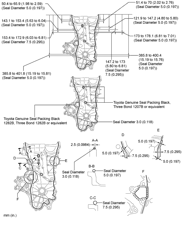
- Apply Seal Packing as Follows:
Area Seal Packing Diameter Application Position from Inside Seal Line Seal Packing Continuous Line Area 3.0 mm (0.118 in.) 2.5 mm (0.098 in.) Toyota Genuine Seal Packing Black, Three Bond 1207B or equivalent Dashed Line Area 4.0 mm (0.156 in.) 3.0 mm (0.118 in.) Toyota Genuine Seal Packing 1282B, Three Bond 1282B or equivalent
Apply adhesive to the threads of the bolt E.
- Adhesive:
- Toyota Genuine Adhesive 1324, Three Bond 1324 or equivalent
Temporarily install the timing chain cover sub-assembly with the 19 bolts.
- NOTICE:
- Remove any oil from the contact surfaces.
- Install the chain cover within 3 minutes after applying seal packing.
- Do not start the engine for at least 2 hours after installing the timing chain cover sub-assembly.
- Bolt Length:
Item Length Bolt A, E 35 mm (1.38 in.) Bolt B 55 mm (2.16 in.) Bolt C 80 mm (3.15 in.) Bolt D 40 mm (1.57 in.)
 |
Install a new gasket.
- NOTICE:
- Remove any oil from the contact surfaces.
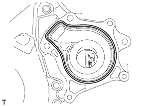 |
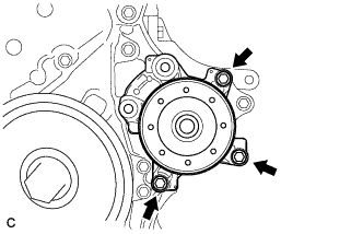
Install the water pump with the 3 bolts.
- Torque:
- 21 N*m{214 kgf*cm, 15 ft.*lbf}
 |
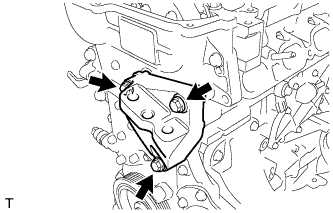
Temporarily install the engine mounting bracket with the 3 bolts.
- NOTICE:
- Install the mounting bracket within 10 minutes after installing the timing chain cover sub-assembly.
- Do not start the engine for at least 2 hours after installation.
- Bolt Length:
Item Length Bolt 80 mm (3.15 in.)
 |
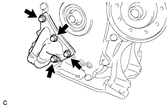
Install 2 new O-rings.
 |
Temporarily install the oil filter bracket with the 4 bolts.
- NOTICE:
- Install the oil filter bracket within 10 minutes after installing the chain cover.
- Do not start the engine for at least 2 hours after installation.
- Bolt Length:
Item Length Bolt 35 mm (1.38 in.)
 |
Fully tighten the timing chain cover sub-assembly with the 26 bolts as shown in the illustration.

- Torque:
- Bolt A, E:
- 26 N*m{260 kgf*cm, 19 ft.*lbf}
- Bolt B, C:
- 51 N*m{520 kgf*cm, 37 ft.*lbf}
- Bolt D:
- 10 N*m{102 kgf*cm, 7 ft.*lbf}
- NOTICE:
- When the contact surfaces are wet, wipe them with oil-free cloth before applying seal packing.
- Install the chain cover within 3 minutes and tighten the bolts within 15 minutes after applying the seal packing.
- Do not start the engine for at least 2 hours after installing.
| 12. INSTALL CRANKSHAFT PULLEY |
Align the pulley set key with the key groove of the pulley.
Using SST, hold the pulley in place and tighten the bolt.
- SST
- 09213-58014(91551-80840)
09330-00021
- Torque:
- 190 N*m{1940 kgf*cm, 140 ft.*lbf}
- NOTICE:
- Check the SST installation positions when installing them to prevent the SST fixing bolts from coming into contact with the timing chain cover sub-assembly.
 |
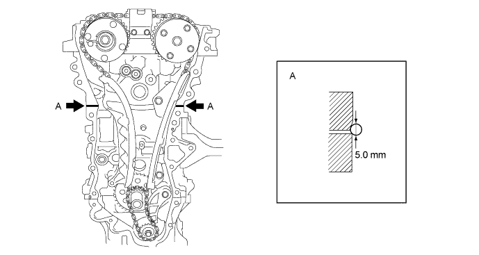
| 13. INSTALL NO. 1 CHAIN TENSIONER ASSEMBLY |
Release the ratchet pawl, then fully push in the plunger and engage the hook to the pin so that the plunger is in the position shown in the illustration.
- NOTICE:
- Make sure that the cam engages the first tooth of the plunger to allow the hook to pass over the pin.
 |
Install a new gasket, bracket and No. 1 chain tensioner with the 2 nuts.
- Torque:
- 12 N*m{122 kgf*cm, 9 ft.*lbf}
- NOTICE:
- If the hook releases the plunger while the chain tensioner is being installed, engage the hook again.
 |
Turn the crankshaft counterclockwise, then disconnect the hook from plunger knock pin.
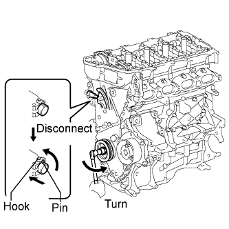 |
Turn the crankshaft clockwise, then check that the plunger is extended.
 |
| 14. INSTALL CYLINDER HEAD COVER SUB-ASSEMBLY |
Install a new gasket to the cylinder head cover.
- NOTICE:
- Remove any oil from the contact surfaces.
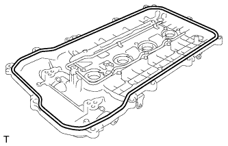 |
Install 3 new gaskets to the No. 1 camshaft bearing cap.
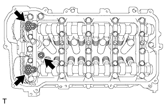 |
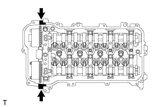
Apply seal packing as shown the illustration.
- Seal packing:
- Toyota Genuine Seal Packing Black, Three Bond 1207B or equivalent
- NOTICE:
- Remove any oil from the contact surfaces.
- Install the cylinder head cover within 3 minutes and tighten the bolts within 15 minutes after applying seal packing.
- Do not start the engine for at least 2 hours after the installation.
 |
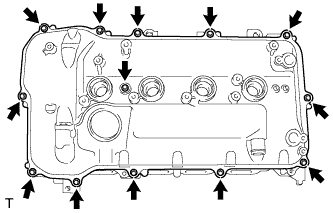
Install the cylinder head cover with a new seal washer and the 13 bolts.
- Torque:
- 10 N*m{102 kgf*cm, 7 ft.*lbf}
 |
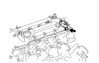
| 15. INSTALL RADIO SETTING CONDENSER |
Install the radio setting condenser with the bolt.
- Torque:
- 10 N*m{102 kgf*cm, 7 ft.*lbf}
 |
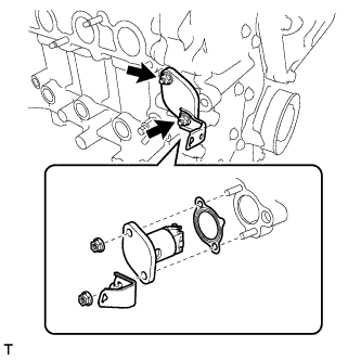
| 16. INSTALL THERMOSTAT |
Install a new gasket on the thermostat.
Install the thermostat to the water inlet with the jiggle valve upward.
- HINT:
- The jiggle valve may be set to within 10° on either side of the indicated position.
 |
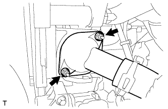
| 17. INSTALL WATER INLET |
Install the water inlet with the 2 nuts.
- Torque:
- 10 N*m{102 kgf*cm, 7 ft.*lbf}
 |
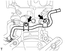
| 18. INSTALL INLET WATER HOSE |
Install the inlet water hose with the 2 clamps.
 |
| 19. INSTALL WATER BY-PASS HOSE |
Install the water by-pass hose with the clamp.
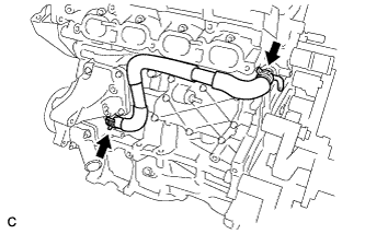
| 20. INSTALL NO. 1 WATER BY-PASS PIPE |
Install the No. 1 water by-pass pipe with the 2 bolts.
- Torque:
- 21 N*m{214 kgf*cm, 16 ft.*lbf}
 |
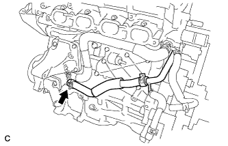
| 21. CONNECT NO. 3 WATER BY-PASS HOSE |
Connect the No. 3 water by-pass hose to the inlet water housing.
 |
| 22. INSTALL VENTILATION HOSE |
Install the ventilation hose.
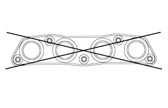
| 23. INSPECT EXHAUST MANIFOLD |
Using a precision straightedge and feeler gauge, measure the warpage on the contact surface of the cylinder head.
- Maximum warpage:
- 0.7 mm (0.028 in.)
- HINT:
- If the warpage is greater than the maximum, replace the manifold.
 |
| 24. INSTALL EXHAUST MANIFOLD |
Install a new gasket onto the exhaust manifold.
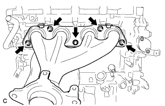 |
Install the exhaust manifold with the 5 nuts.
- Torque:
- 37 N*m{377 kgf*cm, 27 ft.*lbf}
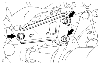
| 25. INSTALL MANIFOLD STAY |
Install the manifold stay with the 3 bolts.
- Torque:
- 43 N*m{439 kgf*cm, 32 ft.*lbf}
 |
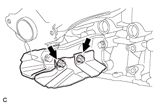
Install the 2 drive shaft heat insulator sub-assemblies with the 2 nuts.
- Torque:
- 18 N*m{184 kgf*cm, 13 ft.*lbf}
 |
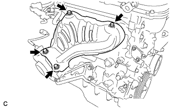
| 26. INSTALL NO. 1 EXHAUST MANIFOLD HEAT INSULATOR |
Install the No. 1 exhaust manifold heat insulator with the 4 bolts.
- Torque:
- 12 N*m{122 kgf*cm, 9 ft.*lbf}
 |
| 27. INSTALL OIL LEVEL DIPSTICK SUB-ASSEMBLY |
Apply engine oil to a new O-ring.
 |
Install the oil level dipstick with the bolt through the new O-ring.
- Torque:
- 21 N*m{214 kgf*cm, 16 ft.*lbf}
| 28. INSTALL IGNITION COIL ASSEMBLY |
Install the 4 ignition coils with the 4 bolts.
- Torque:
- 10 N*m{102 kgf*cm, 7 ft.*lbf}
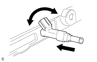
| 29. INSTALL FUEL INJECTOR ASSEMBLY |
Install 4 new injector vibration insulators to the 4 fuel injector assemblies.
 |
Install 4 new injector vibration insulators to the 4 fuel injector assemblies.
Apply a light coat of gasoline or spindle oil to the contact surfaces of the the O-rings of the fuel injector assemblies.
While turning the fuel injector assembly left and right, install it onto the fuel delivery pipe sub-assembly.
- NOTICE:
- Do not twist the O-ring.
- After installing the fuel injectors, check that they turn smoothly.
 |
| 30. INSTALL NO. 1 DELIVERY PIPE SPACER |
Install the 2 No. 1 delivery pipe spacers onto the cylinder head.
Text in Illustration *a Delivery Pipe Side *b Cylinder Head Side - NOTICE:
- Install the No. 1 delivery pipe spacers in the correct direction.
 |
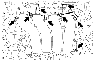
| 31. INSTALL FUEL DELIVERY PIPE SUB-ASSEMBLY |
Install the fuel delivery pipe sub-assembly with the 4 fuel injector assemblies, then temporarily install the 2 bolts.
- NOTICE:
- Do not drop the fuel injectors when installing the fuel delivery pipe sub-assembly.
- Check that the fuel injector assemblies rotate smoothly after installing the fuel delivery pipe sub-assembly.
 |
Tighten the 2 bolts to the specified torque.
- Torque:
- 21 N*m{214 kgf*cm, 15 ft.*lbf}
|
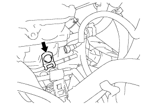
Install the bolt to secure the fuel delivery pipe sub-assembly.
- Torque:
- 21 N*m{214 kgf*cm, 15 ft.*lbf}
 |
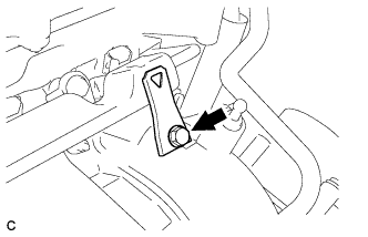
Install the wire harness bracket with the bolt.
- Torque:
- 5.0 N*m{51 kgf*cm, 44 in.*lbf}
 |
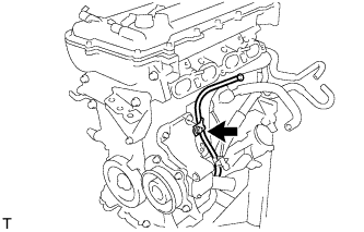
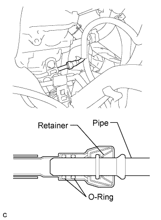
| 32. CONNECT FUEL TUBE SUB-ASSEMBLY |
Insert the fuel tube sub-assembly connector into the fuel delivery pipe until a "click" sound can be heard.
- NOTICE:
- Check that there are no scratches or foreign matter around the contact surfaces of the fuel tube connector and pipe before performing this work.
- After connecting the fuel tube, check that the fuel tube connector and pipe are securely connected by pulling on them.
 |
Install a new No. 2 fuel pipe clamp (Type B).
 |
Install a new No. 2 fuel pump clamp (Type A).
 |
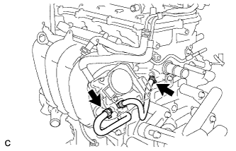
| 33. INSTALL INTAKE MANIFOLD |
Install a new gasket to the intake manifold.
Install the intake manifold and intake manifold stay with the 4 bolts and 2 nuts.
- Torque:
- 28 N*m{286 kgf*cm, 21 ft.*lbf}
 |
Connect the 2 water by-pass hoses.
 |
Connect the ventilation hose to the intake manifold.
Install the air tube with the 2 bolts.
- Torque:
- 10 N*m{102 kgf*cm, 7 ft.*lbf}
Install the wire harness bracket.
- Torque:
- 10 N*m{102 kgf*cm, 7 ft.*lbf}
| 34. REMOVE ENGINE STAND |
Attach the engine to a sling device with the chain block.
Remove the engine from the engine stand.
| 35. INSTALL ENGINE ASSEMBLY WITH TRANSAXLE |
- HINT: