Lighting System Engine Switch Illumination Circuit
DESCRIPTION
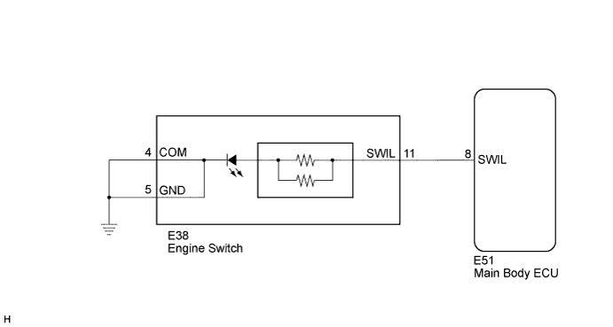
WIRING DIAGRAM
INSPECTION PROCEDURE
PERFORM ACTIVE TEST USING TECHSTREAM
INSPECT ENGINE SWITCH
CHECK HARNESS OR CONNECTOR (ENGINE SWITCH - MAIN BODY ECU AND BODY GROUND)
LIGHTING SYSTEM - Engine Switch Illumination Circuit |
DESCRIPTION
When either of the following conditions is met, the engine switch illumination comes on.- Light control switch is in TAIL position.
- Interior light is turned on by the illuminated entry system.
WIRING DIAGRAM
INSPECTION PROCEDURE
| 1.PERFORM ACTIVE TEST USING TECHSTREAM |
Connect the Techstream to the DLC3.
Turn the ignition switch to ON.
Turn the Techstream on.
Enter the following menus: Body Electrical / Main Body / Active Test.
Check the operation.
Main Body (Main Body ECU)Tester Display
| Test Part
| Control Range
| Diagnostic Note
|
Indicator for Lighting
| Engine switch illumination (All doors are closed)
| ON/OFF
| -
|
- OK:
- Engine switch illumination comes on.
Remove the engine switch.
Connect a (+) lead from the battery to terminal 11 and a (-) lead to terminal 4 or 5.
Check that the illumination comes on.
- OK:
- Engine switch illumination comes on.
| 3.CHECK HARNESS OR CONNECTOR (ENGINE SWITCH - MAIN BODY ECU AND BODY GROUND) |
Disconnect the E51 main body ECU connector.
Disconnect the E38 engine switch connector.
Measure the resistance according to the value(s) in the table below.
- Standard Resistance:
Tester Connection
| Condition
| Specified Condition
|
E38-11 (SWIL) - E51-8 (SWIL)
| Always
| Below 1 Ω
|
E38-4 (COM) or E38-5 (GND) - Body ground
| Always
| Below 1 Ω
|
E51-8 (SWIL) - Body ground
| Always
| 10 kΩ or higher
|
| | REPAIR OR REPLACE HARNESS OR CONNECTOR |
|
|
| OK |
|
|
|
| REPLACE MAIN BODY ECU (INSTRUMENT PANEL JUNCTION BLOCK) |
|