Audio And Visual System (W/O Multi-Display) Microphone Circuit Between Microphone And Radio Receiver
DESCRIPTION
WIRING DIAGRAM
INSPECTION PROCEDURE
INSPECT RADIO RECEIVER ASSEMBLY
CONFIRM MODEL
CHECK HARNESS AND CONNECTOR (TELEPHONE MICROPHONE ASSEMBLY - RADIO RECEIVER ASSEMBLY)
INSPECT TELEPHONE MICROPHONE ASSEMBLY
INSPECT TELEPHONE MICROPHONE ASSEMBLY
CHECK HARNESS AND CONNECTOR (TELEPHONE MICROPHONE ASSEMBLY - RADIO RECEIVER ASSEMBLY)
INSPECT MAP LIGHT ASSEMBLY
INSPECT MAP LIGHT ASSEMBLY
REPLACE TELEPHONE MICROPHONE ASSEMBLY
AUDIO AND VISUAL SYSTEM (w/o Multi-display) - Microphone Circuit between Microphone and Radio Receiver |
DESCRIPTION
This circuit sends the microphone voice signal from the telephone microphone assembly to the radio receiver assembly.Using this circuit, the radio receiver assembly sends power to the telephone microphone assembly, and the telephone microphone assembly sends microphone voice signals to the radio receiver assembly (w/o sliding roof system).Using this circuit, the radio receiver assembly sends power to the map light assembly (telephone microphone assembly), and the map light assembly sends microphone voice signals to the radio receiver assembly (w/ sliding roof system).
WIRING DIAGRAM
INSPECTION PROCEDURE
| 1.INSPECT RADIO RECEIVER ASSEMBLY |
Disconnect the E114 radio receiver assembly connector.
Measure the voltage according to the value(s) in the table below.
- Standard Voltage:
Tester Connection
| Condition
| Specified Condition
|
E114-4 (MACC) - Body ground
| Ignition switch ON
| 4 to 6 V
|
Measure the resistance according to the value(s) in the table below.
- Standard Resistance:
Tester Connection
| Condition
| Specified Condition
|
E114-18 (SGND) - Body ground
| Always
| Below 1 Ω
|
E114-19 (MIC-) - Body ground
| Always
| Below 1 Ω
|
Text in Illustration*a
| Component without harness connected
(Radio Receiver Assembly)
|
- Result:
Condition
| Proceed to
|
w/o sliding roof system
| A
|
w/ sliding roof system
| B
|
| 3.CHECK HARNESS AND CONNECTOR (TELEPHONE MICROPHONE ASSEMBLY - RADIO RECEIVER ASSEMBLY) |
Disconnect the E114 radio receiver assembly connector.
Disconnect the O9 telephone microphone assembly connector.
Measure the resistance according to the value(s) in the table below.
- Standard Resistance:
Tester Connection
| Condition
| Specified Condition
|
E114-6 (SNS2) - O9-3 (SNS2)
| Always
| Below 1 Ω
|
E114-5 (MIC+) - O9-2 (MIC+)
| Always
| Below 1 Ω
|
E114-19 (MIC-) - O9-4 (MIC-)
| Always
| Below 1 Ω
|
E114-4 (MACC) - O9-1 (MACC)
| Always
| Below 1 Ω
|
E114-6 (SNS2) - Body ground
| Always
| 10 kΩ or higher
|
E114-5 (MIC+) - Body ground
| Always
| 10 kΩ or higher
|
E114-19 (MIC-) - Body ground
| Always
| 10 kΩ or higher
|
E114-4 (MACC) - Body ground
| Always
| 10 kΩ or higher
|
E114-18 (SGND) - Body ground
| Always
| 10 kΩ or higher
|
| | REPAIR OR REPLACE HARNESS OR CONNECTOR |
|
|
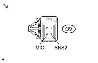
| 4.INSPECT TELEPHONE MICROPHONE ASSEMBLY |
Disconnect the O9 telephone microphone assembly connector.
Measure the resistance according to the value(s) in the table below.
- Standard Resistance:
Tester Connection
| Condition
| Specified Condition
|
O9-3 (SNS2) - O9-4 (MIC-)
| Always
| Below 1 Ω
|
Text in Illustration*a
| Component without harness connected
(Telephone Microphone Assembly)
|
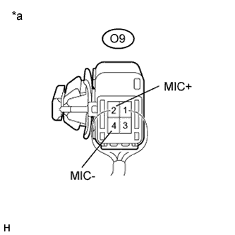
| 5.INSPECT TELEPHONE MICROPHONE ASSEMBLY |
Reconnect the O9 telephone microphone assembly connector.
Reconnect the E114 radio receiver assembly connector.
Turn the ignition switch to ACC.
Connect an oscilloscope to terminals 2 (MIC+) and 4 (MIC-) of the O9 telephone microphone assembly connector.
Check the waveform of the telephone microphone assembly using the oscilloscope.
- Result:
Result
| Proceed to
|
A waveform synchronized with the voice input to the telephone microphone assembly is output
| A
|
A waveform synchronized with the voice input to the telephone microphone assembly is not output
| B
|
Text in Illustration*a
| Component with harness connected
(Telephone Microphone Assembly)
|
| 6.CHECK HARNESS AND CONNECTOR (TELEPHONE MICROPHONE ASSEMBLY - RADIO RECEIVER ASSEMBLY) |
Disconnect the E114 radio receiver assembly connector.
Disconnect the O10 map light assembly connector.
Measure the resistance according to the value(s) in the table below.
- Standard Resistance:
Tester Connection
| Condition
| Specified Condition
|
E114-6 (SNS2) - O10-9 (SNS2)
| Always
| Below 1 Ω
|
E114-5 (MIC+) - O10-11 (MI1+)
| Always
| Below 1 Ω
|
E114-19 (MIC-) - O10-10 (MIC-)
| Always
| Below 1 Ω
|
E114-4 (MACC) - O10-12 (ACC)
| Always
| Below 1 Ω
|
E114-6 (SNS2) - Body ground
| Always
| 10 kΩ or higher
|
E114-5 (MIC+) - Body ground
| Always
| 10 kΩ or higher
|
E114-19 (MIC-) - Body ground
| Always
| 10 kΩ or higher
|
E114-4 (MACC) - Body ground
| Always
| 10 kΩ or higher
|
E114-18 (SGND) - Body ground
| Always
| 10 kΩ or higher
|
| | REPAIR OR REPLACE HARNESS OR CONNECTOR |
|
|
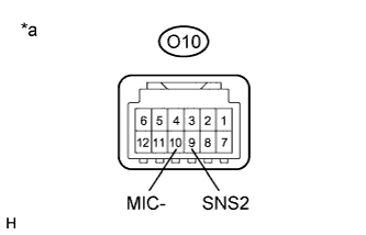
| 7.INSPECT MAP LIGHT ASSEMBLY |
Disconnect the O10 map light assembly connector.
Measure the resistance according to the value(s) in the table below.
- Standard Resistance:
Tester Connection
| Condition
| Specified Condition
|
O10-9 (SNS2) - O10-10 (MIC-)
| Always
| Below 1 Ω
|
Text in Illustration*a
| Component without harness connected
(Map Light Assembly)
|
| 8.INSPECT MAP LIGHT ASSEMBLY |
Reconnect the O10 map light assembly connector.
Reconnect the E114 radio receiver assembly connector.
Turn the ignition switch to ACC.
Connect an oscilloscope to terminals 11 (MI1+) and 10 (MIC-) of the O10 map light assembly connector.
Check the waveform of the telephone microphone assembly using the oscilloscope.
- Result:
Result
| Proceed to
|
A waveform synchronized with the voice input to the map light assembly is output
| A
|
A waveform synchronized with the voice input to the map light assembly is not output
| B
|
Text in Illustration*a
| Component with harness connected
(Map Light Assembly)
|
| 9.REPLACE TELEPHONE MICROPHONE ASSEMBLY |
Replace the telephone microphone assembly (COROLLA_ZRE142 RM000001Q0103IX.html).
Check if the same malfunction recurs.
- Result:
Result
| Proceed to
|
Malfunction does not recur
(returns to normal)
| A
|
Malfunction recurs
| B
|