Air Conditioning System (For Manual Air Conditioning System) Ptc Heater Circuit
DESCRIPTION
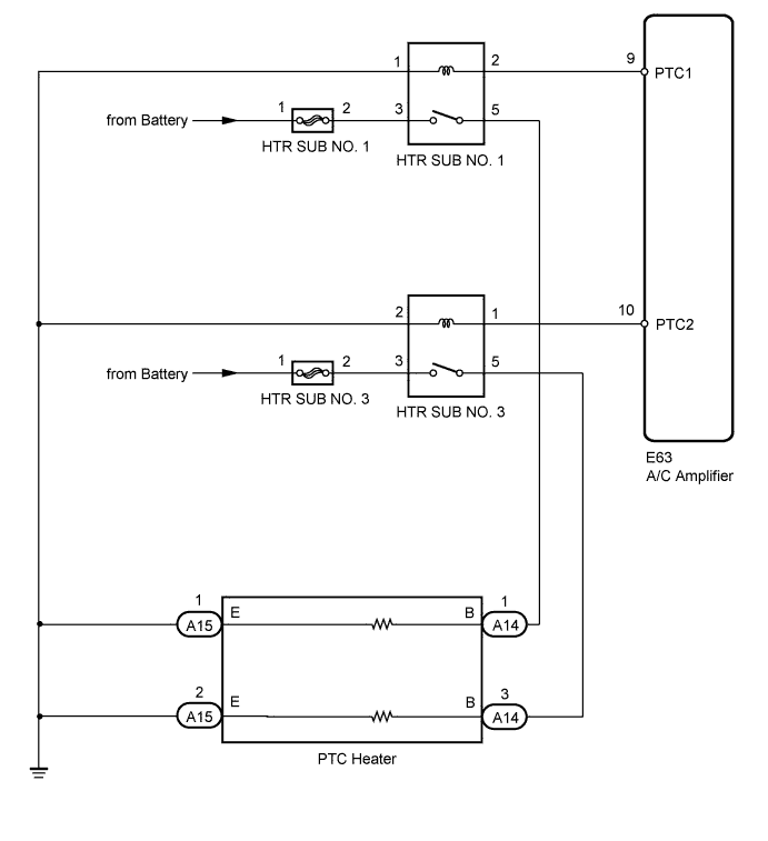
WIRING DIAGRAM
INSPECTION PROCEDURE
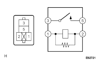
INSPECT RELAY (HTR SUB NO. 1, HTR SUB NO. 3)
CHECK HARNESS AND CONNECTOR (ENGINE ROOM RELAY BLOCK - A/C AMPLIFIER, BODY GROUND)
INSPECT AIR CONDITIONING AMPLIFIER
INSPECT PTC HEATER
CHECK HARNESS AND CONNECTOR (PTC HEATER - BATTERY)
AIR CONDITIONING SYSTEM (for Manual Air Conditioning System) - PTC Heater Circuit |
DESCRIPTION
The PTC heater is installed in the heater unit and operates when the coolant temperature is low and normal heater operation is insufficient.The A/C amplifier switches the circuit in the PTC relay and operates the PTC heater when the operating conditions (the coolant temperature is below 65°C (149°F), setting temperature is MAX. HOT, ambient temperature is below 10°C (50°F) and blower switch is not OFF) are met.The PTC heater controls the number of the heater elements to be heated based on the electrical load and the amount of voltage generated. Therefore, when inspecting the PTC heater, be sure to turn off other electrical devices.
WIRING DIAGRAM
INSPECTION PROCEDURE
- NOTICE:
- Inspect the fuses for circuits related to this system before performing the following inspection procedure.
| 1.INSPECT RELAY (HTR SUB NO. 1, HTR SUB NO. 3) |
Remove the HTR SUB No. 1 and HTR SUB No. 3 relays from the engine room relay block and junction block.
Measure the resistance according to the value(s) in the table below.
- Standard Resistance:
Tester Connection
| Specified Condition
|
3 - 5
| 10 kΩ or higher
|
3 - 5
| Below 1 Ω
(When battery voltage applied to terminals 1 and 2)
|
Install the HTR SUB No. 1 and HTR SUB No. 3 relays to the engine room relay block and junction block.
| | REPLACE RELAY (HTR SUB NO. 1, HTR SUB NO. 3) |
|
|
| 2.CHECK HARNESS AND CONNECTOR (ENGINE ROOM RELAY BLOCK - A/C AMPLIFIER, BODY GROUND) |
Disconnect the connector from the A/C amplifier.
Remove the HTR SUB No. 1 and HTR SUB No. 3 fuses from the engine room relay block and junction block.
Measure the resistance according to the value(s) in the table below.
- Standard Resistance:
Tester Connection
| Condition
| Specified Condition
|
E63-9 (PTC1) - HTR SUB No. 1 relay terminal 2
| Always
| Below 1 Ω
|
E63-10 (PTC2) - HTR SUB No. 3 relay terminal 1
| Always
| Below 1 Ω
|
E63-9 (PTC1) - Body ground
| Always
| 10 kΩ or higher
|
E63-10 (PTC2) - Body ground
| Always
| 10 kΩ or higher
|
HTR SUB No. 1 relay terminal 1 - Body ground
| Always
| Below 1 Ω
|
HTR SUB No. 3 relay terminal 2 - Body ground
| Always
| Below 1 Ω
|
| | REPAIR OR REPLACE HARNESS OR CONNECTOR |
|
|
| 3.INSPECT AIR CONDITIONING AMPLIFIER |
Reconnect the connector to the A/C amplifier.
Remove the A/C amplifier with the connectors still connected.
Measure the voltage according to the value(s) in the table below.
- Standard Voltage:
Tester Connection
| Condition
| Specified Condition
|
E63-9 (PTC1) - Body ground
| Ignition switch ON
Temperature setting: MAX. HOT
Ambient temperature: 10°C (50°F) or lower
Engine coolant temperature: 65°C (149°F) or lower
Light control switch: OFF
Blower switch: OFF
| Below 1 V
|
E63-9 (PTC1) - Body ground
| Engine running (1250 rpm or higher)
Temperature setting: MAX. HOT
Ambient temperature: 10°C (50°F) or lower
Engine coolant temperature: 65°C (149°F) or lower
Light control switch: OFF
Blower switch: ON
| 11 to 14 V
|
E63-10 (PTC2) - Body ground
| Ignition switch ON
Temperature setting: MAX. HOT
Ambient temperature: 10°C (50°F) or lower
Engine coolant temperature: 65°C (149°F) or lower
Light control switch: OFF
Blower switch: OFF
| Below 1 V
|
E63-10 (PTC2) - Body ground
| Engine running (1250 rpm or higher)
Temperature setting: MAX. HOT
Ambient temperature: 10°C (50°F) or lower
Engine coolant temperature: 65°C (149°F) or lower
Light control switch: OFF
Blower switch: ON
| 11 to 14 V
|
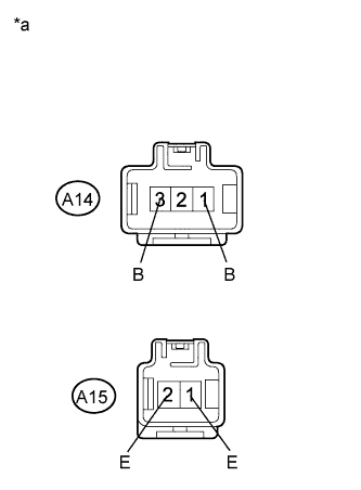
Text in Illustration*a
| Component with harness connected
(A/C Amplifier)
|
Disconnect the connector from the PTC heater.
Measure the resistance according to the value(s) in the table below.
- Standard Resistance:
Tester Connection
| Condition
| Specified Condition
|
A14-1 (B) - A15-1 (E)
| Always
| Below 1 Ω
|
A14-3 (B) - A15-2 (E)
| Always
| Below 1 Ω
|
Text in Illustration*a
| Component without harness connected
(PTC Heater)
|
| 5.CHECK HARNESS AND CONNECTOR (PTC HEATER - BATTERY) |

|
Measure the voltage according to the value(s) in the table below.
- Standard Voltage:
Tester Connection
| Condition
| Specified Condition
|
A14-1 (B) - Body ground
| Ignition switch ON
Temperature setting: MAX. HOT
Ambient temperature: 10°C (50°F) or lower
Engine coolant temperature: 65°C (149°F) or lower
Light control switch: OFF
Blower switch: OFF
| Below 1 V
|
A14-1 (B) - Body ground
| Engine running (1250 rpm or higher)
Temperature setting: MAX. HOT
Ambient temperature: 10°C (50°F) or lower
Engine coolant temperature: 65°C (149°F) or lower
Light control switch: OFF
Blower switch: ON
| 11 to 14 V
|
A14-3 (B) - Body ground
| Ignition switch ON
Temperature setting: MAX. HOT
Ambient temperature: 10°C (50°F) or lower
Engine coolant temperature: 65°C (149°F) or lower
Light control switch: OFF
Blower switch: OFF
| Below 1 V
|
A14-3 (B) - Body ground
| Engine running (1250 rpm or higher)
Temperature setting: MAX. HOT
Ambient temperature: 10°C (50°F) or lower
Engine coolant temperature: 65°C (149°F) or lower
Light control switch: OFF
Blower switch: ON
| 11 to 14 V
|
Text in Illustration*a
| Front view of wire harness connector
(to PTC Heater)
|
| | REPAIR OR REPLACE HARNESS OR CONNECTOR |
|
|
| OK |
|
|
|
| REPAIR OR REPLACE HARNESS OR CONNECTOR (PTC HEATER - BODY GROUND) |
|