Front Stabilizer Bar Removal
PLACE FRONT WHEELS FACING STRAIGHT AHEAD
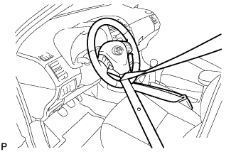
SECURE STEERING WHEEL
REMOVE COLUMN HOLE COVER SILENCER SHEET
SEPARATE NO. 2 STEERING INTERMEDIATE SHAFT ASSEMBLY
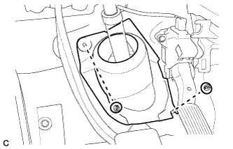
SEPARATE NO. 1 STEERING COLUMN HOLE COVER SUB-ASSEMBLY
REMOVE FRONT WHEELS
SEPARATE TIE ROD END SUB-ASSEMBLY LH
SEPARATE TIE ROD END SUB-ASSEMBLY RH
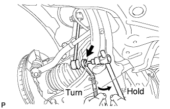
REMOVE FRONT STABILIZER LINK ASSEMBLY LH
REMOVE FRONT STABILIZER LINK ASSEMBLY RH
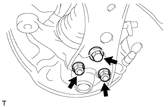
SEPARATE FRONT LOWER SUSPENSION ARM LH
SEPARATE FRONT LOWER SUSPENSION ARM RH
REMOVE FRONT SUSPENSION CROSSMEMBER SUB-ASSEMBLY
REMOVE FRONT STABILIZER BAR
REMOVE NO. 1 FRONT STABILIZER BAR BUSHING
Front Stabilizer Bar -- Removal |
| 1. PLACE FRONT WHEELS FACING STRAIGHT AHEAD |
Secure the steering wheel with the seat belt in order to prevent rotation.
- HINT:
- This operation is useful to prevent damage to the spiral cable.
| 3. REMOVE COLUMN HOLE COVER SILENCER SHEET |
Turn back the floor carpet, and remove the 2 clips and column hole cover silencer sheet.
| 4. SEPARATE NO. 2 STEERING INTERMEDIATE SHAFT ASSEMBLY |
Put matchmarks on the No. 2 steering intermediate shaft assembly and the steering intermediate shaft.
Remove the bolt and separate the No. 2 steering intermediate shaft assembly from the steering intermediate shaft.
| 5. SEPARATE NO. 1 STEERING COLUMN HOLE COVER SUB-ASSEMBLY |
Remove clips A and the No. 1 steering column hole cover sub-assembly and disengage clip B from the body.
- NOTICE:
- Do not damage clips A and B.
| 7. SEPARATE TIE ROD END SUB-ASSEMBLY LH |
Remove the cotter pin and the nut.
Install SST to the tie rod end.
- SST
- 09960-20010(09961-02060)
- NOTICE:
- Make sure that the upper ends of the tie rod end and SST are aligned.
Using SST, separate the tie rod end from the steering knuckle.
- SST
- 09960-20010(09961-02010)
- CAUTION:
- Apply grease to the threads of the bolt and the tip of SST.
- NOTICE:
- Be sure to tighten the string firmly to secure SST to the steering knuckle to prevent SST from falling off.
- Install SST with the center nut so that A and B are parallel. Otherwise, the dust cover may be damaged.
- Be sure to place the wrench on the part indicated in the illustration.
- Do not damage the front disc brake dust cover.
- Do not damage the ball joint dust cover.
- Do not damage the steering knuckle.
| 8. SEPARATE TIE ROD END SUB-ASSEMBLY RH |
- HINT:
- Perform the same procedure as the LH side.
| 9. REMOVE FRONT STABILIZER LINK ASSEMBLY LH |
Remove the nut and separate the stabilizer link assembly LH from the front shock absorber with coil spring.
- HINT:
- If the ball joint turns together with the nut, use a hexagon wrench (6 mm) to hold the stud bolt.
Remove the nut and the stabilizer link assembly LH from the front stabilizer bar.
- HINT:
- If the ball joint turns together with the nut, use a hexagon wrench (6 mm) to hold the stud bolt.
| 10. REMOVE FRONT STABILIZER LINK ASSEMBLY RH |
- HINT:
- Perform the same procedure as the LH side.
| 11. SEPARATE FRONT LOWER SUSPENSION ARM LH |
Remove the bolt and 2 nuts, and separate the front lower suspension arm from the lower ball joint.
| 12. SEPARATE FRONT LOWER SUSPENSION ARM RH |
- HINT:
- Perform the same procedure as the LH side.
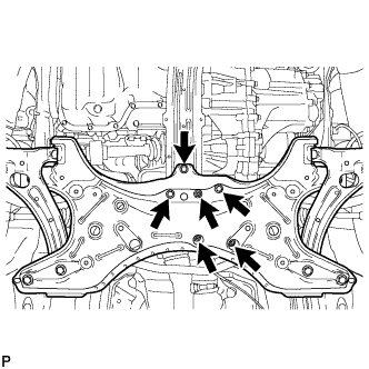
| 13. REMOVE FRONT SUSPENSION CROSSMEMBER SUB-ASSEMBLY |
Remove the 3 bolts and 3 nuts.
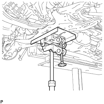
Using a transmission jack or equivalent, support the front suspension crossmember sub-assembly.
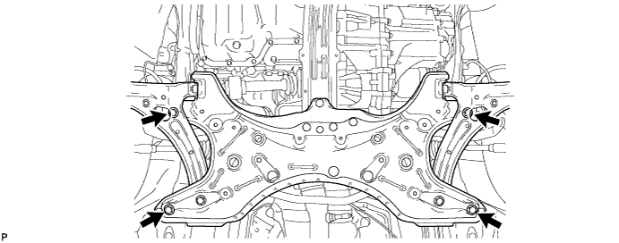
Remove the 4 bolts and front suspension crossmember sub-assembly.
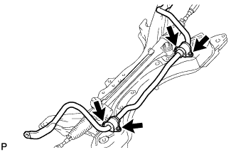
| 14. REMOVE FRONT STABILIZER BAR |
Remove the 4 bolts, 2 No. 1 front stabilizer brackets and front stabilizer bar from the front suspension crossmember.
| 15. REMOVE NO. 1 FRONT STABILIZER BAR BUSHING |
Remove the 2 No. 1 front stabilizer bar bushings from the front stabilizer bar.