Cylinder Head Gasket Removal
REMOVE ENGINE ASSEMBLY WITH TRANSAXLE
INSTALL ENGINE STAND
REMOVE INTAKE MANIFOLD
DISCONNECT FUEL TUBE SUB-ASSEMBLY
REMOVE FUEL DELIVERY PIPE SUB-ASSEMBLY
REMOVE FUEL INJECTOR ASSEMBLY
REMOVE IGNITION COIL ASSEMBLY
REMOVE OIL LEVEL DIPSTICK SUB-ASSEMBLY
REMOVE NO. 1 EXHAUST MANIFOLD HEAT INSULATOR
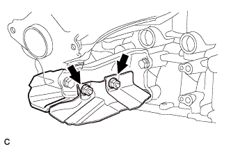
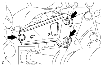
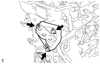
REMOVE MANIFOLD STAY
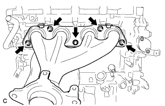
REMOVE EXHAUST MANIFOLD
REMOVE VENTILATION HOSE
DISCONNECT NO. 3 WATER BY-PASS HOSE
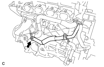
REMOVE NO. 1 WATER BY-PASS PIPE
REMOVE WATER BY-PASS HOSE
REMOVE INLET WATER HOSE
REMOVE WATER INLET
REMOVE THERMOSTAT
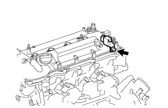
REMOVE RADIO SETTING CONDENSER
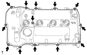
REMOVE CYLINDER HEAD COVER SUB-ASSEMBLY
SET NO. 1 CYLINDER TO TDC/COMPRESSION
REMOVE CRANKSHAFT PULLEY
REMOVE NO. 1 CHAIN TENSIONER ASSEMBLY
REMOVE TIMING CHAIN COVER SUB-ASSEMBLY
REMOVE TIMING CHAIN COVER OIL SEAL
REMOVE CHAIN TENSIONER SLIPPER
REMOVE NO. 1 CHAIN VIBRATION DAMPER
REMOVE CHAIN SUB-ASSEMBLY
REMOVE NO. 2 CHAIN VIBRATION DAMPER
INSPECT CAMSHAFT TIMING GEAR ASSEMBLY
INSPECT CAMSHAFT TIMING EXHAUST GEAR ASSEMBLY
REMOVE CAMSHAFT TIMING GEAR ASSEMBLY
REMOVE CAMSHAFT TIMING EXHAUST GEAR ASSEMBLY
REMOVE CAMSHAFT BEARING CAP
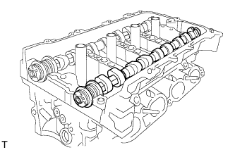
REMOVE CAMSHAFT
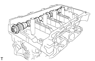
REMOVE NO. 2 CAMSHAFT
REMOVE NO. 1 CAMSHAFT BEARING
REMOVE NO. 1 VALVE ROCKER ARM SUB-ASSEMBLY
REMOVE VALVE LASH ADJUSTER ASSEMBLY
REMOVE NO. 2 CAMSHAFT BEARING
REMOVE CAMSHAFT HOUSING SUB-ASSEMBLY
REMOVE CYLINDER HEAD SUB-ASSEMBLY
REMOVE CYLINDER HEAD GASKET
INSPECT NO. 1 VALVE ROCKER ARM SUB-ASSEMBLY
INSPECT VALVE LASH ADJUSTER ASSEMBLY
INSPECT CYLINDER HEAD SET BOLT
Cylinder Head Gasket -- Removal |
| 1. REMOVE ENGINE ASSEMBLY WITH TRANSAXLE |
- HINT:
- COROLLA_ZRE142 RM000002WH607RX.html.
Install the engine to an engine stand.
| 3. REMOVE INTAKE MANIFOLD |
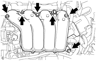
Disconnect the 5 wire harness clamps.
Remove the 2 engine cover joints and separate the wire harness clamp bracket.
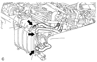
Disconnect the vapor feed hose, ventilation hose and vacuum hose from the intake manifold.
Remove the 4 bolts, 2 nuts, intake manifold stay and intake manifold.
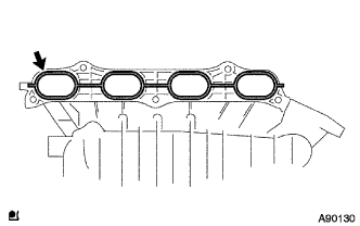
Remove the gasket from the intake manifold.
Remove the bolt and wire harness clamp bracket.
Using a "TORX" socket wrench (E6), remove the 2 stud bolts from the intake manifold.
| 4. DISCONNECT FUEL TUBE SUB-ASSEMBLY |
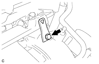
Remove the No. 2 fuel pipe clamp (Type A).
Remove the No. 2 fuel pipe clamp (Type B).
Using SST, disconnect the fuel tube sub-assembly.
- SST
- 09268-21011
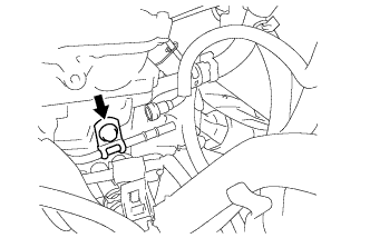
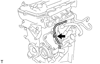
| 5. REMOVE FUEL DELIVERY PIPE SUB-ASSEMBLY |
Remove the bolt and wire harness bracket.
Remove the 2 bolts.
Remove the bolt and the fuel delivery pipe sub-assembly.
Remove the 2 No. 1 delivery pipe spacers.
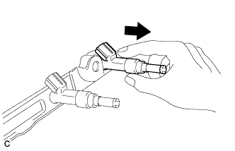
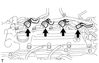
| 6. REMOVE FUEL INJECTOR ASSEMBLY |
Pull the 4 fuel injector assemblies out of the fuel delivery pipe sub-assembly.
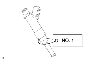
For reinstallation, attach a tag or label to the injector shaft.
- NOTICE:
- Prevent entry of foreign objects by covering the fuel injector with a plastic bag.
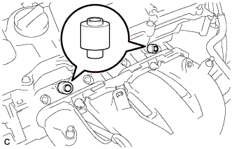
Remove the O-rings from the fuel injector assemblies.
Remove the 4 injector vibration insulators.
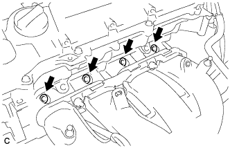
| 7. REMOVE IGNITION COIL ASSEMBLY |
Disconnect the 4 ignition coil connectors.
Remove the 4 bolts and 4 ignition coils.
- NOTICE:
- When removing each ignition coil, do not damage the plug cap on the engine head cover opening or the upper edge of the spark plug tube.
| 8. REMOVE OIL LEVEL DIPSTICK SUB-ASSEMBLY |
Remove the bolt and oil level dipstick.
Remove the O-ring from the oil level dipstick.
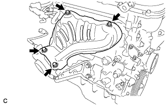
| 9. REMOVE NO. 1 EXHAUST MANIFOLD HEAT INSULATOR |
Remove the 4 bolts and No. 1 exhaust manifold heat insulator.
Remove the 2 nuts and 2 drive shaft heat insulator sub-assemblies.
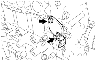
Remove the 3 bolts and manifold stay.
| 11. REMOVE EXHAUST MANIFOLD |
Remove the 5 nuts and exhaust manifold and gasket.
| 12. REMOVE VENTILATION HOSE |
Remove the ventilation hose.
| 13. DISCONNECT NO. 3 WATER BY-PASS HOSE |
Disconnect the No. 3 water by-pass hose from the water inlet housing.
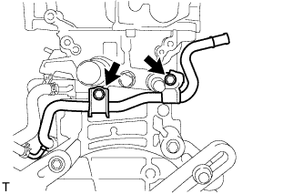
| 14. REMOVE NO. 1 WATER BY-PASS PIPE |
Remove the 2 bolts and No. 1 water by-pass pipe.
| 15. REMOVE WATER BY-PASS HOSE |
Remove the clamp and water by-pass hose.
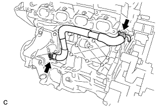
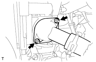
| 16. REMOVE INLET WATER HOSE |
Remove the 2 clamps and inlet water hose.
Remove the 2 nuts and water inlet.
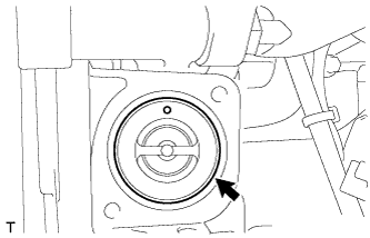
Remove the thermostat.
Remove the gasket from the thermostat.
| 19. REMOVE RADIO SETTING CONDENSER |
Remove the bolt and radio setting condenser.
| 20. REMOVE CYLINDER HEAD COVER SUB-ASSEMBLY |
Remove the 13 bolts, seal washer and cylinder head cover.
- NOTICE:
- Be careful not to drop any of the gaskets into the engine when removing the cylinder head cover because the gaskets may stick to the cylinder head cover.
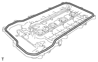
Remove the cylinder head cover gasket.
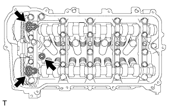
Remove the 3 gaskets from the camshaft bearing cap.
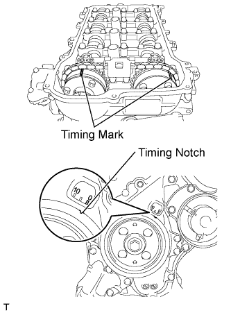
| 21. SET NO. 1 CYLINDER TO TDC/COMPRESSION |
Turn the crankshaft pulley until its groove and the timing mark "0" of the timing chain cover are aligned.
Check that each timing mark of the camshaft timing gear and sprocket are aligned with each timing mark located as shown in the illustration. If not, turn the crankshaft 1 revolution (360°) to align the timing marks as shown in the illustration.
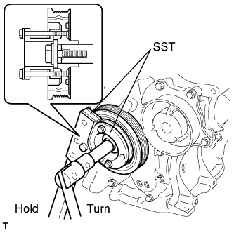
| 22. REMOVE CRANKSHAFT PULLEY |
Using SST, hold the pulley in place and loosen the pulley bolt.
- SST
- 09213-58014(91551-80840)
09330-00021
- NOTICE:
- Check the SST installation positions when installing them to prevent the SST fixing bolts from coming into contact with the timing chain cover sub-assembly.
Using SST, remove the crankshaft pulley and pulley bolt.
- SST
- 09950-50013(09951-05010,09952-05010,09953-05020,09954-05021)
| 23. REMOVE NO. 1 CHAIN TENSIONER ASSEMBLY |
Remove the 2 nuts, bracket, tensioner and gasket.
- NOTICE:
- Do not turn the crankshaft without the chain tensioner installed.
| 24. REMOVE TIMING CHAIN COVER SUB-ASSEMBLY |
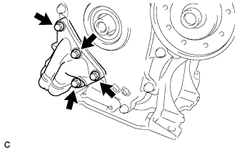
Remove the 3 bolts and engine mounting bracket.
Remove the 4 bolts and oil filter bracket.
Remove the 2 O-rings.
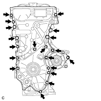
Remove the 19 bolts.
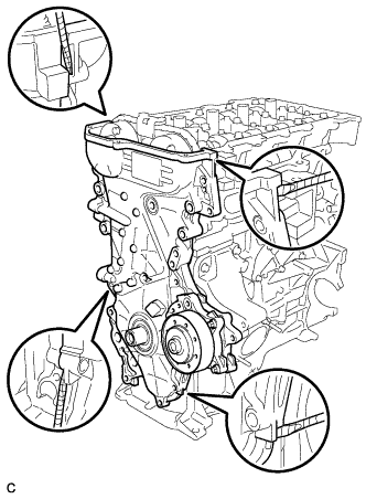
Remove the timing chain cover by prying between the timing chain cover and cylinder head or cylinder block with a screwdriver.
- NOTICE:
- Be careful not to damage the contact surfaces of the timing chain cover, cylinder block, and cylinder head.
- HINT:
- Tape the screwdriver tip before use.
Remove the 3 O-rings.
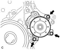
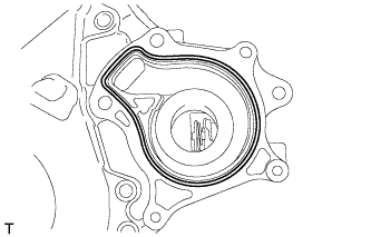
Remove the 3 bolts and water pump.
Remove the gasket.
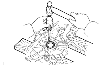
| 25. REMOVE TIMING CHAIN COVER OIL SEAL |
Using a screwdriver and hammer, remove the oil seal.
- NOTICE:
- Be careful not to damage the timing chain cover.
- HINT:
- Tape the screwdriver tip before use.
| 26. REMOVE CHAIN TENSIONER SLIPPER |
Remove the chain tensioner slipper.
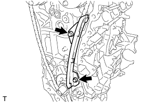
| 27. REMOVE NO. 1 CHAIN VIBRATION DAMPER |
Remove the 2 bolts and No. 1 chain vibration damper.
| 28. REMOVE CHAIN SUB-ASSEMBLY |
Hold the hexagonal portion of the camshaft with a wrench and turn the camshaft timing gear assembly counterclockwise to loosen the chain between the camshaft timing gears.
With the chain loosened, release the chain from the camshaft timing gear assembly and place it on the camshaft timing gear assembly.
- HINT:
- Be sure to release the chain from the sprocket completely.
Turn the camshaft clockwise to return it to the original position and remove the chain.
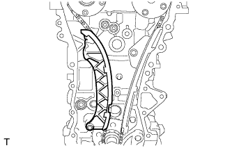
| 29. REMOVE NO. 2 CHAIN VIBRATION DAMPER |
Remove the 2 bolts and No. 2 chain vibration damper.
| 30. INSPECT CAMSHAFT TIMING GEAR ASSEMBLY |
Inspect the lock of the camshaft timing gear.
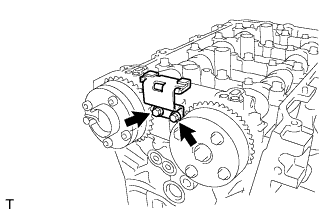
After cleaning and degreasing the VVT oil hole on the intake side of the No. 1 camshaft bearing cap, completely seal the oil hole with adhesive tape or equivalent as shown in the illustration to prevent air from leaking.
- NOTICE:
- Be sure to cover the oil hole completely because air leaks due to insufficient sealing will prevent the lock pin from being released.
Prick a hole in the tape covering the oil hole as shown in the illustration. (Procedure A)
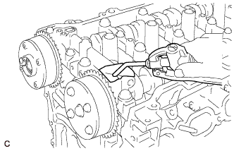
Apply approximately 150 kPa (1.5 kgf/cm2, 22 psi) of air pressure to the hole pricked in procedure A to release the lock pin.
- NOTICE:
- If air leaks out, reattach the adhesive tape.
- Cover the oil hole with a piece of cloth when applying air pressure to prevent oil from spraying.
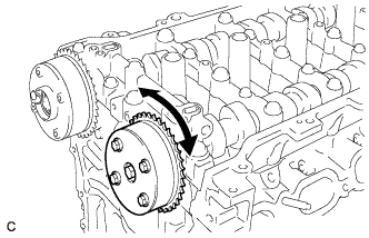
Forcibly turn the camshaft timing gear assembly in the advance direction (counterclockwise).
- HINT:
- Depending on the air pressure applied, the camshaft timing gear assembly may turn in the advance direction without assistance by hand.
Turn the camshaft timing gear assembly within its movable range (26.5 to 28.5°) 2 or 3 times without turning it to the most retarded position. Make sure that the camshaft timing gear assembly turns smoothly.
Remove the adhesive tape from the No. 1 camshaft bearing cap.
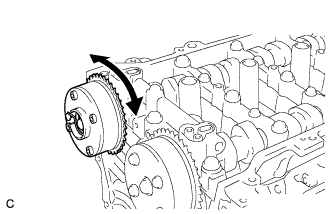
| 31. INSPECT CAMSHAFT TIMING EXHAUST GEAR ASSEMBLY |
Check the lock of the camshaft timing exhaust gear.
After cleaning and degreasing the VVT oil hole on the exhaust side of the No. 1 camshaft bearing cap, completely seal the oil hole with adhesive tape or equivalent as shown in the illustration to prevent air from leaking.
- NOTICE:
- Be sure to cover the oil hole completely because air leaks due to insufficient sealing will prevent the lock pin from being released.
Prick a hole in the tape covering the oil hole as shown in the illustration. (Procedure B)
Apply approximately 200 kPa (2.0 kgf/cm2, 28 psi) of air pressure to the hole pricked in procedure B to release the lock pin.
- NOTICE:
- If air leaks out, reattach the adhesive tape.
- Cover the oil hole with a shop rag or a piece of cloth when applying air pressure to prevent oil from spraying.
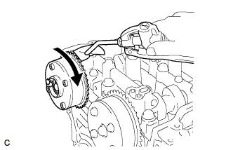
Using a screwdriver with its tip wrapped with tape, forcibly turn the camshaft timing exhaust gear in the retard direction (clockwise).
- NOTICE:
- Be sure to keep the camshaft timing exhaust gear in the retard direction using a screwdriver. If the gear is released, it will return to the most advanced position automatically due to force from the spring.
- Do not damage the camshaft timing exhaust gear.
Using a screwdriver with its tip wrapped with tape, turn the camshaft timing exhaust gear within its movable range (19 to 21°) 2 or 3 times without turning it to the most advanced position. Make sure that the camshaft timing exhaust gear turns smoothly.
Remove the adhesive tape from the No. 1 camshaft bearing cap.
| 32. REMOVE CAMSHAFT TIMING GEAR ASSEMBLY |
Remove the flange bolt while holding the hexagonal portion of the camshaft, then remove the camshaft timing gear assembly.
- NOTICE:
- Before removing the camshaft timing gear, make sure that the lock pin has been released.
- Be sure not to remove the other 4 bolts.
- Keep the camshaft timing gear assembly horizontal while removing it from the camshaft.
| 33. REMOVE CAMSHAFT TIMING EXHAUST GEAR ASSEMBLY |
Remove the flange bolt while holding the hexagonal portion of the camshaft, then remove the camshaft timing exhaust gear assembly.
- NOTICE:
- Be sure not to remove the other 4 bolts.
- Keep the camshaft timing exhaust gear assembly horizontal while removing it from the camshaft.
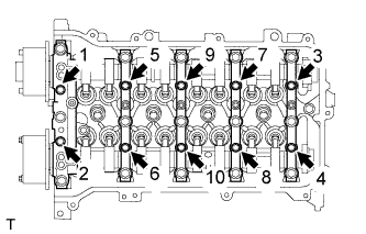
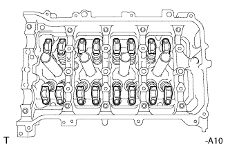
| 34. REMOVE CAMSHAFT BEARING CAP |
Uniformly loosen and remove the 10 bearing cap bolts in the sequence shown in the illustration.
Uniformly loosen and remove the 15 bearing cap bolts in the sequence shown in the illustration.
- NOTICE:
- Uniformly loosen the bolts while keeping the camshaft level.
Remove the 5 bearing caps.
- HINT:
- Arrange the removed parts in the correct order.
Remove the camshaft.
| 36. REMOVE NO. 2 CAMSHAFT |
Remove the No. 2 camshaft.
| 37. REMOVE NO. 1 CAMSHAFT BEARING |
Remove the 2 No. 1 camshaft bearings.
- HINT:
- Arrange the removed parts in the correct order.
| 38. REMOVE NO. 1 VALVE ROCKER ARM SUB-ASSEMBLY |
Remove the 16 valve rocker arms.
- HINT:
- Arrange the removed parts in the correct order.
| 39. REMOVE VALVE LASH ADJUSTER ASSEMBLY |
Remove the 16 valve lash adjusters from the cylinder head.
- HINT:
- Arrange the removed parts in the correct order.
| 40. REMOVE NO. 2 CAMSHAFT BEARING |
Remove the 2 No. 2 camshaft bearings.
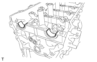
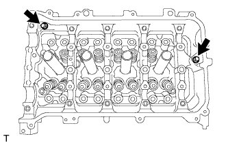
| 41. REMOVE CAMSHAFT HOUSING SUB-ASSEMBLY |
Remove the 2 bolts.
Remove the camshaft housing by prying between the cylinder head and camshaft housing with a screwdriver.
- NOTICE:
- Be careful not to damage the contact surfaces of the cylinder head and camshaft housing.
- HINT:
- Tape the screwdriver tip before use.
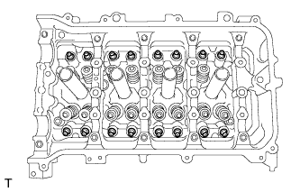
| 42. REMOVE CYLINDER HEAD SUB-ASSEMBLY |
Using several steps, uniformly loosen and remove the 10 cylinder head bolts and 10 plate washers with a 10 mm bi-hexagon wrench in the sequence shown in the illustration.
- NOTICE:
- Head warpage or cracking could result from removing the bolts in the wrong order.
Using a screwdriver with its tip wrapped with tape, pry between the cylinder head and cylinder block, and remove the cylinder head.
- NOTICE:
- Be careful not to damage the contact surfaces of the cylinder head and cylinder block.
| 43. REMOVE CYLINDER HEAD GASKET |
Remove the cylinder head gasket.
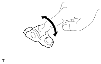
| 44. INSPECT NO. 1 VALVE ROCKER ARM SUB-ASSEMBLY |
Turn the roller by hand to check that it turns smoothly.
- HINT:
- If the roller does not turn smoothly, replace the valve rocker arm sub-assembly.
| 45. INSPECT VALVE LASH ADJUSTER ASSEMBLY |
- NOTICE:
- Keep the lash adjuster free of dirt and foreign matter.
- Only use clean engine oil.
Place the lash adjuster into a container filled with engine oil.
Insert the tip of SST into the lash adjuster plunger and use the tip to press down on the check ball inside the plunger.
- SST
- 09276-75010
Squeeze SST and the lash adjuster together to move the plunger up and down 5 to 6 times.
Check the movement of the plunger and bleed it.
- OK:
- Plunger moves up and down.
- NOTICE:
- When bleeding the high-pressure chamber, make sure that the tip of SST is actually pressing the check ball as shown in the illustration. If the check ball is not pressed, the high-pressure chamber will not be bled.
After bleeding, remove SST. Then try to quickly and firmly press the plunger by hand.
- OK:
- Plunger is very difficult to move.
If the result is not as specified, replace the lash adjuster.
| 46. INSPECT CYLINDER HEAD SET BOLT |
Using a vernier caliper, measure the length of the cylinder head set bolt from the seat to the end.
- Standard bolt length:
- 146.8 to 148.2 mm (5.7795 to 5.8346 in.)
- Maximum bolt length:
- 149.2 mm (5.874 in.)
If the bolt length is greater than the maximum, replace the cylinder head set bolt.
Using a vernier caliper, measure the minimum diameter of the elongated thread at the measuring point.
- Standard outside diameter:
- 9.77 to 9.96 mm (0.3846 to 0.3921 in.)
- Minimum outside diameter:
- 9.4 mm (0.3701 in.)
- HINT:
- Using a straightedge, visually check thinner areas of the threaded part of the cylinder head set bolt.
If the diameter is less than the minimum, replace the cylinder head set bolt.